

Injection molding process for multi-air-channel auxiliary plastic mold
A plastic mold and multi-air channel technology, applied in the direction of coating, etc., can solve the problems of short service life of parts, low pass rate of parts, affecting parts and other problems, achieve perfect quality, improve smoothness, and eliminate internal stress Effect
- Summary
- Abstract
- Description
- Claims
- Application Information
AI Technical Summary
Problems solved by technology
Method used
Image

Examples
specific Embodiment 1
[0027] Such as figure 1 As shown, it is a multi-air channel auxiliary plastic mold injection molding process described in this embodiment, which includes the following steps:
[0028] Step (1) Plastic mold design:
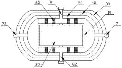
[0029] Described plastic mold comprises plastic mold body 10, and described plastic mold body 10 is provided with mold cavity 20, and described plastic mold body 10 is also provided with the multi-air channel that cooperates with described mold cavity 20, and described multi-air channel It includes a first airway 30, a second airway 40, a third airway 50 and a partial airway 60, and the first airway 30, the second airway 40 and the third airway 50 are provided with matching The first airway inlet 71 and the first airway outlet 72 , and the partial airway 60 is provided with a second airway inlet 81 and a second airway outlet 82 .
[0030] Step (2) mold pre-cooling stage:
[0031] The cold air flow is injected into the third air channel 50 through the first air c...
specific Embodiment 2
[0046] Such as figure 1 As shown, it is a multi-air channel auxiliary plastic mold injection molding process described in this embodiment, which includes the following steps:
[0047] Step (1) Plastic mold design:
[0048]Described plastic mold comprises plastic mold body 10, and described plastic mold body 10 is provided with mold cavity 20, and described plastic mold body 10 is also provided with the multi-air channel that cooperates with described mold cavity 20, and described multi-air channel It includes a first airway 30, a second airway 40, a third airway 50 and a partial airway 60, and the first airway 30, the second airway 40 and the third airway 50 are provided with matching The first airway inlet 71 and the first airway outlet 72 , and the partial airway 60 is provided with a second airway inlet 81 and a second airway outlet 82 .
[0049] Step (2) mold pre-cooling stage:
[0050] The cold air flow is injected into the third air channel 50 through the first air ch...
specific Embodiment 3
[0065] Such as figure 1 As shown, it is a multi-air channel auxiliary plastic mold injection molding process described in this embodiment, which includes the following steps:
[0066] Step (1) Plastic mold design:
[0067] Described plastic mold comprises plastic mold body 10, and described plastic mold body 10 is provided with mold cavity 20, and described plastic mold body 10 is also provided with the multi-air channel that cooperates with described mold cavity 20, and described multi-air channel It includes a first airway 30, a second airway 40, a third airway 50 and a partial airway 60, and the first airway 30, the second airway 40 and the third airway 50 are provided with matching The first airway inlet 71 and the first airway outlet 72 , and the partial airway 60 is provided with a second airway inlet 81 and a second airway outlet 82 .
[0068] Step (2) mold pre-cooling stage:
[0069] The cold air flow is injected into the third air channel 50 through the first air c...
PUM
 Abstract
Description
Claims
Application Information