
Flue gas analysis device based on ultraviolet difference technology, and flue gas analysis method

A technology of flue gas analysis and ultraviolet difference, which is applied in the field of flue gas analysis devices based on ultraviolet difference technology, can solve the problems of not meeting the monitoring requirements, increasing the difficulty of on-site maintenance, increasing the complexity of the system, etc., achieving strong anti-background gas interference, Improve measurement accuracy and improve the effect of spectral signal intensity

Active Publication Date: 2017-11-07
天津国阳科技发展有限公司
View PDF8 Cites 10 Cited by
  • Summary
  • Abstract
  • Description
  • Claims
  • Application Information

AI Technical Summary

Problems solved by technology

[0003] Due to the complexity of the flue gas components in the ultra-low emission site and the low concentration of sulfur dioxide and nitrogen oxide emissions, most of the flue gas analyzers currently installed on the site are conventional range analyzers, which can no longer meet the monitoring requirements. The existing flue gas analysis The instrument mainly has the following problems: 1. Some flue gas analyzers using infrared technology are easily affected by background gas interference in low-concentration areas; 2. Some ultraviolet flue gas analyzers use multiple reflection measurement cells to improve detection sensitivity. The multi-reflection measurement cell increases the complexity of the system, is less stable than the straight-through cell and increases the difficulty of on-site maintenance

Method used

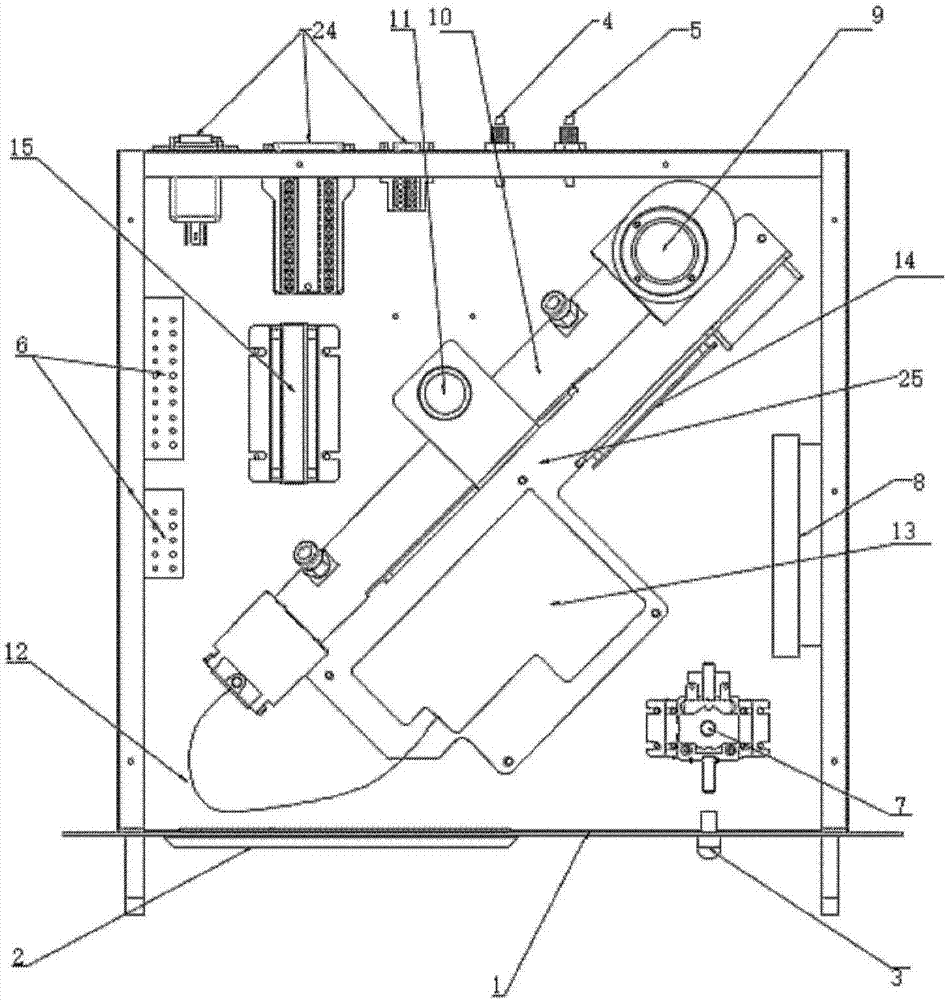
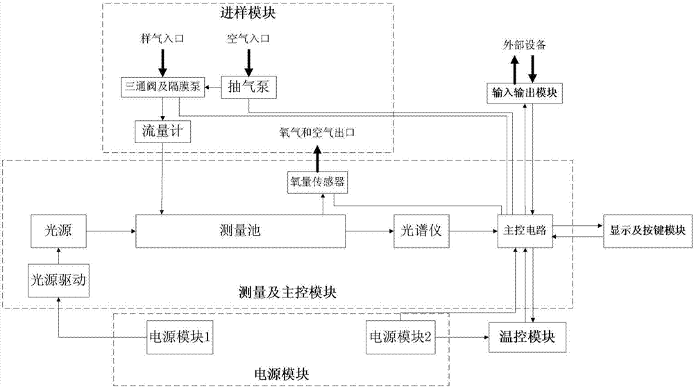
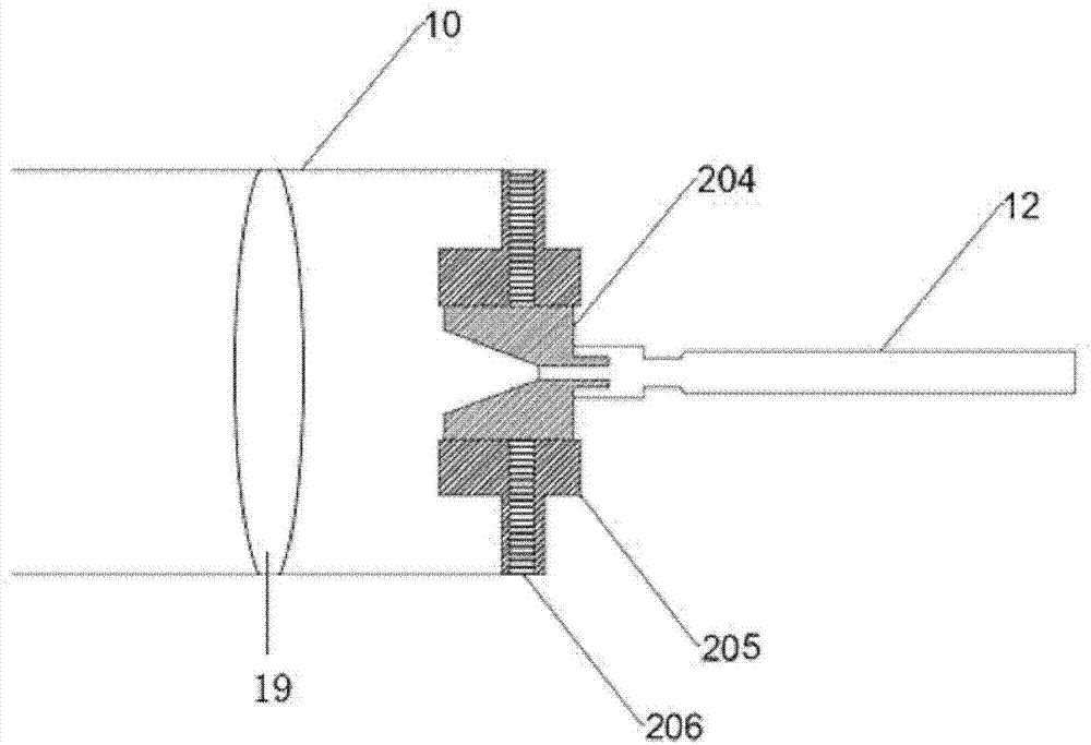

Image

  • Flue gas analysis device based on ultraviolet difference technology, and flue gas analysis method
  • Flue gas analysis device based on ultraviolet difference technology, and flue gas analysis method
  • Flue gas analysis device based on ultraviolet difference technology, and flue gas analysis method

Examples


Embodiment Construction

[0040] In order to make the purpose, technical solutions and advantages of the present invention clearer, the present invention will be described in further detail below in conjunction with specific embodiments and with reference to the accompanying drawings, the contents of which are sufficient to enable any person skilled in the art to understand the technical content of the present invention and According to implement.

[0041] When using ultraviolet differential absorption spectroscopy for detection, the light absorption of the sample gas can be divided into two parts: one part changes rapidly with the wavelength and constitutes the narrow-band fine structure of the spectrum, this part is only related to the characteristic absorption of the gas to be measured; the other part changes with the wavelength Slowly changing, constituting the broadband structure of the spectrum, this part is not only related to the characteristics of some gases, but also related to the scattering of...


PUM


Abstract

The invention relates to a flue gas analysis device based on an ultraviolet difference technology, and a flue gas analysis method. The flue gas analysis device sequentially comprises an ultraviolet light source, a measuring cell, an optical fiber and a spectrograph, wherein a focusing lens and an optical fiber connection adjustment mechanism are arranged at the end, close to the optical fiber, of the measuring cell; the optical fiber connection adjustment mechanism is used for adjusting the front and back translation, relative to the measuring cell, of a longitudinal end face of the optical fiber so as to utilize the axial chromatic aberration of the focusing lens to enable ultraviolet light emitted by the ultraviolet light source to couple different spectral energy distributions in the optical fiber, thus obtaining the position of the longitudinal end face of the optical fiber with the maximum spectral energy distribution at the absorption wavelengths of all flue gas components by means of multiple adjustments during detection, improving the signal to noise ratio and enhancing the detection sensitivity of concentrations of all the flue gas components. The device and the method can adapt to detection of different sample gases to be detected.

Description

technical field [0001] The invention relates to a spectrum analysis device, in particular to a flue gas analysis device and method based on ultraviolet differential technology. Background technique [0002] In December 2015, the executive meeting of the State Council decided to fully implement ultra-low emission and energy-saving transformation of coal-fired units before 2020. The latest Air Pollution Prevention and Control Law came into effect on January 1, 2016. Local environmental protection departments have successively issued the most stringent emission standards in history, and the emission concentrations of smoke, sulfur dioxide, and nitrogen oxides should not exceed 10mg / m 3 、35mg / m 3 , 50mg / m 3 . [0003] Due to the complexity of the flue gas components in the ultra-low emission site and the low concentration of sulfur dioxide and nitrogen oxide emissions, most of the flue gas analyzers currently installed on site are conventional range analyzers, which can no l...

Claims


Application Information

Patent Timeline
IPC IPC(8): G01N21/33
Inventor 刘超任贺良黄明生徐可欣
Owner 天津国阳科技发展有限公司
Learn More