Strong mutual-coupling ultra-wideband wide-angle scanning dual-polarized conformal phased-array antenna

A wide-angle scanning and ultra-wideband technology, which is applied in the field of antenna engineering, can solve problems such as conformal processing of unarrayed units, inability to realize ultra-wideband scanning, and influence of carrier aerodynamic layout, so as to improve scanning standing wave and isolation, Lower load requirements and lower processing costs

Active Publication Date: 2017-11-10
UNIV OF ELECTRONICS SCI & TECH OF CHINA
View PDF5 Cites 26 Cited by
  • Summary
  • Abstract
  • Description
  • Claims
  • Application Information

AI Technical Summary

Problems solved by technology

[0003] To sum up, the problems existing in the existing technology are: the conformal shape of traditional antennas is greatly limited in bandwidth due to the influence of mutual coupling between units and the difficulty of impedance matching, and ultra-wideband scanning cannot be realized ; The antenna based on the strong mutual coupling effect, which only performs conformal arrangement of the feed end, does not perform conformal treatment on the array elements, which has a great impact on the aerodynamic layout of the carrier, thus limiting its application

Method used


Image

  • Strong mutual-coupling ultra-wideband wide-angle scanning dual-polarized conformal phased-array antenna
  • Strong mutual-coupling ultra-wideband wide-angle scanning dual-polarized conformal phased-array antenna
  • Strong mutual-coupling ultra-wideband wide-angle scanning dual-polarized conformal phased-array antenna

Examples


Embodiment Construction

[0036] In order to make the object, technical solution and advantages of the present invention more clear, the present invention will be further described in detail below in conjunction with the examples. It should be understood that the specific embodiments described here are only used to explain the present invention, not to limit the present invention.

[0037] The application principle of the present invention will be further described below in conjunction with the accompanying drawings.

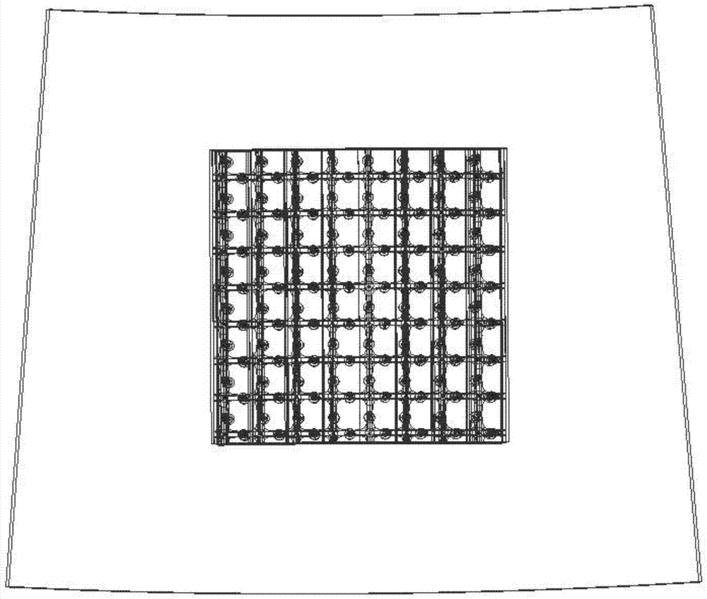
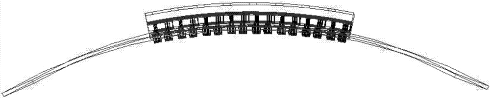
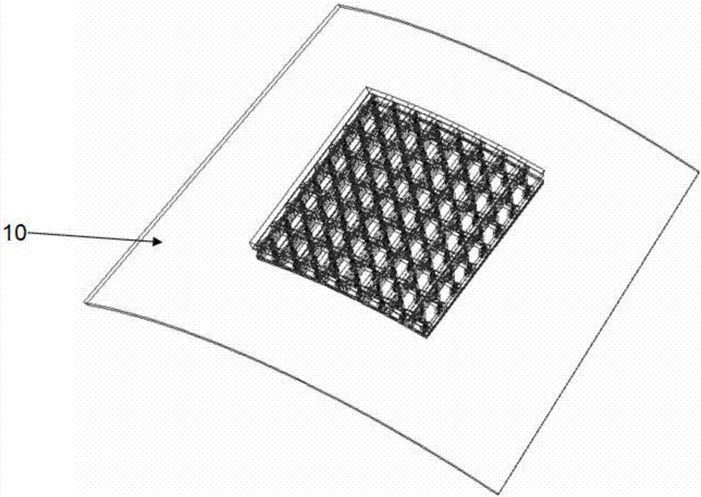
[0038] Such as Figure 1-Figure 4 As shown, embodiments of the present invention consist of a layer of periodic structures printed with closely spaced conformal dipole units. Its structure mainly includes a conformal dielectric substrate 1; a vertically crossed conformal dipole unit 2 printed on the upper layer of the conformal dielectric substrate; a circular metal patch 3 printed on the lower layer of the conformal dielectric substrate; A conformal dielectric layer 4 that has been du...


PUM


Abstract

The invention belongs to the technical field of antenna engineering, and discloses a strong mutual-coupling ultra-wideband wide-angle scanning dual-polarized conformal phased-array antenna. The strong mutual-coupling ultra-wideband wide-angle scanning dual-polarized conformal phased-array antenna comprises a conformal dielectric substrate, conformal dipole units, a circular metal patch, a conformal dielectric layer, a conformal dielectric impedance matching layer, a metal ground matching layer, an unbalance feeding structure, five grounding metallized through holes, a microwave coaxial cable and a metallized frustum-shaped carrier, wherein the conformal dipole units are printed on an upper layer of the conformal dielectric substrate, and placed in a vertical intersection way; the circular metal patch is printed on a lower layer of the conformal dielectric substrate; the conformal dielectric layer is positioned below the conformal dielectric substrate, and subjected to hole digging treatment; the conformal dielectric impedance matching layer is positioned above the conformal dielectric substrate; and the microwave coaxial cable is used for feeding the unbalance feeding structure. The weight of the novel antenna is only 70 percent that of a conventional phased array, so that the requirement on the load carrying of a carrier is lowered greatly. The metal ground matching layer is used, so that an original complex matching circuit is omitted; the machining difficulty is lowered greatly; and the machining cost of the antenna on engineering applications is lowered.

Description

technical field [0001] The invention belongs to the technical field of antenna engineering, in particular to a strong mutual coupling ultra-wide bandwidth angular scanning dual-polarization conformal phased array antenna. Background technique [0002] As an important characterization of phased array antennas, array antennas reflect the particularity and complexity of phased array antennas themselves, and also condense the advantages of phased array antennas. When each array unit is distributed on the surface of the electronic system platform, and the array surface matches the shape of the carrier platform, a conformal array antenna (Conformal Antenna Array, CAA), referred to as "conformal array", is formed. The outer surface theory of the carrier The surface can be any complex curved surface, of course, it can also be a plane, so the traditional planar array antenna can be regarded as a special case of conformal array. It can be seen that "conformal array antenna" is not a ...

Claims


Application Information

Patent Timeline
Patent Type & Authority Applications(China)
IPC IPC(8): H01Q1/38H01Q1/50H01Q5/25H01Q5/335H01Q5/48H01Q21/24
CPCH01Q1/38H01Q1/50H01Q5/25H01Q5/335H01Q5/48H01Q21/24
Inventor 杨仕文肖乾树陈益凯鲍鸿飞刘坤宁屈世伟
Owner UNIV OF ELECTRONICS SCI & TECH OF CHINA
Why Eureka
Try Eureka