
Low-power, high-speed and high-precision comparator circuit

A comparator circuit, high-precision technology, applied in the field of microelectronics, can solve problems such as large offset and return noise, slow speed, etc.

Pending Publication Date: 2017-11-10
天津力芯伟业科技有限公司
View PDF0 Cites 9 Cited by
  • Summary
  • Abstract
  • Description
  • Claims
  • Application Information

AI Technical Summary

Problems solved by technology

The op amp structure comparator can distinguish small input signals, but at a slower speed; the latch is faster, but can only distinguish larger input signals, and at the same time, the offset and return noise are also large. In the actual application process , the comparator has high requirements for speed and precision, and using either comparator alone cannot meet the requirements, and the two comparators are often cascaded to form a high-speed and high-precision comparator

Method used


Image

  • Low-power, high-speed and high-precision comparator circuit
  • Low-power, high-speed and high-precision comparator circuit
  • Low-power, high-speed and high-precision comparator circuit

Examples


Embodiment Construction

[0014] The present invention will be further described below in conjunction with the accompanying drawings.

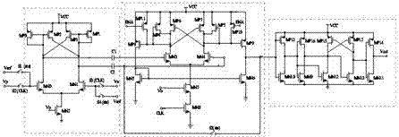
[0015] A low-power high-speed high-precision comparator circuit (see figure 1 ), including sequentially connected four input sampling switches S1, S2, S3, S4, preamplifiers, coupling capacitors C1, C2, secondary preamplifiers, output latches, wherein the sampling switches S1, S2, S3, S4, It is used to connect the input to the fixed reference level Vref during the reset phase, and to connect the input to the differential input signal Vn, Vp during the comparison time.

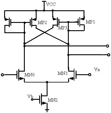
[0016] The preamplifier uses a cross-structured P transistor load to amplify the differential input signal. It is necessary to ensure that the preamplifier has sufficient bandwidth and gain to reduce the total offset voltage equivalent to the input of the ultra-high-speed comparator and improve the comparator. accuracy of the device.

[0017] Coupling capacitors C1 and C2 are used to store the offset v...


PUM


Abstract

The invention is a low-power, high-speed, high-precision comparator circuit compatible with standard CMOS technology, characterized in that: the low-power, high-speed, high-precision comparator circuit includes sequentially connected input sampling switches, preamplifiers, and two-stage preamplifiers And latch; input sampling switch includes a pair of switches for sampling input signal and a pair of switches for sampling reference voltage; The terminal output further increases the amplification factor, and the capacitor link between the secondary amplifier and the preamplifier eliminates the offset input offset and output offset. Control the working state of the latch; its advantage lies in: the low power consumption, high speed and high precision comparator circuit can greatly improve the speed and precision of the comparator.

Description

technical field [0001] The invention belongs to the technical field of microelectronics and relates to a comparator circuit with low power consumption, high speed and high precision compatible with a semiconductor integrated circuit and a standard CMOS process. Background technique [0002] The comparator converts the input analog signal into a digital signal, which is an important interface from analog to digital, and is widely used in circuits such as analog-to-digital converters and digital-to-analog converters. In metal-oxide-semiconductor devices, electronic components are susceptible to changes in operating characteristics, which typically appear as shifts in threshold voltage levels. For example, in a comparator circuit, mismatches in the differential pair and mismatches in the current sources can cause comparator offset, which is a voltage offset by affecting the difference between the input voltage and the reference voltage. The comparison performance limits the ac...

Claims


Application Information

Patent Timeline
IPC IPC(8): H03K5/24
CPCH03K5/2472
Inventor 陈力颖
Owner 天津力芯伟业科技有限公司
Learn More