Electric drive device, and electric power steering device

一种电动驱动、电动机的技术,应用在动力转向机构、转向机构、电子换向器等方向,能够解决电流、电压及转矩易发生振荡等问题

Active Publication Date: 2017-11-10
MITSUBISHI ELECTRIC CORP
View PDF12 Cites 9 Cited by
  • Summary
  • Abstract
  • Description
  • Claims
  • Application Information

AI Technical Summary

Problems solved by technology

[0010] In addition, in an AC rotating machine with multiple sets of stator windings, in the case of mutual inductance among multiple sets of stator windings, since the current of one stator winding will affect the current of another stator winding, the current of each stator winding , voltage and torque are prone to oscillation

Method used


Image

  • Electric drive device, and electric power steering device
  • Electric drive device, and electric power steering device
  • Electric drive device, and electric power steering device

Examples


Embodiment approach 1

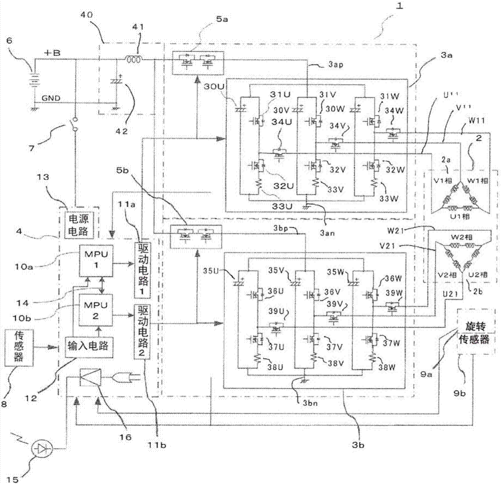
[0057] Hereinafter, the electric drive device according to Embodiment 1 of the present invention will be described in detail based on the drawings. figure 1 It is a circuit configuration diagram of the electric drive device according to Embodiment 1 of the present invention, and shows a case where the electric drive device is configured as an electric power steering device. in figure 1 Here, the electric power steering apparatus 100 includes a control unit 1, a motor (hereinafter referred to as a motor) constituted by a three-phase brushless motor, etc. 2, a control circuit section 4, a first rotation sensor 9a, and a second rotation sensor 9b.

[0058] The control unit 1 includes a dual redundant system with the same structure, including a control circuit unit 4 equipped with a first MPU 10a and a second MPU 10b, a first inverter circuit 3a, a second inverter circuit 3b, and a first inverter The first power supply relay 5a connected in series with the high-voltage side DC termina...

Embodiment approach 2

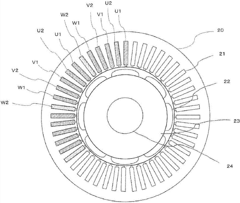
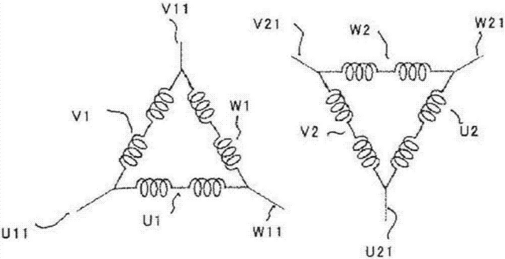
[0136] Next, Embodiment 2 will be described. Figure 6A Is a transverse cross-sectional view of the electric motor in the electric drive device according to the second embodiment of the present invention, Figure 6B It is a circuit diagram showing a stator winding of a motor in an electric drive device according to Embodiment 2 of the present invention. Embodiment 1 figure 1 The circuit structure diagram of is applicable to the case of Embodiment 2. Hereinafter, the same reference numerals indicate the same or equivalent parts. Figure 6A Is the same as in embodiment 1 Figure 2A The corresponding drawings. In the following description, the difference from the case of Embodiment 1 will be mainly described.

[0137] in Figure 6A Among them, the stator 20 in which 12 slots 21 are arranged on the inner periphery is formed by laminating thin steel plates. A rotor 23 is arranged concentrically at the center of the stator 20, and 10-pole field poles 22 made of permanent magnets are a...


PUM


Abstract

The present invention is configured from an electric motor (2), and a control unit (1) for driving the motor. The motor (2) has, provided to a single rotor (23), a stator (20) provided with two independent coil winding groups. The control unit (1) is mainly configured from: an input circuit (12) for inputting various pieces of information; output circuits for driving the coil winding groups of the motor (2); and MPUs (10a, 10b) which calculate control quantities on the basis of the information from the input circuit (12), and output control signals to the output circuits. The MPUs are provided as two separate independent units, and are configured so as to be capable of supplying and turning off currents to the respective winding groups of the motor. The MPUs are respectively provided with integrated CPUs (10c, 10d), and trigger circuits (17) which use prescribed periods as trigger signals. Both of the CPUs are configured so as to synchronize and output at least control commands in accordance with the trigger signals.

Description

Technical field [0001] The present invention relates to an electric drive device with multiple microprocessors (hereinafter referred to as MPU) in consideration of a redundant system of control units, and more particularly to an electric drive device in which multiple MPUs cooperate to control the output control amount, and use The electric power steering device of the electric drive device. Background technique [0002] As is well known, as an electric drive device that uses an electric motor as a drive source to drive a non-driven object, for example, there is an electric power steering device mounted on a vehicle. The electric power steering device is a device that uses a control unit to drive an electric motor so that the electric motor generates an output torque corresponding to the steering torque applied to the steering wheel by the driver of the vehicle, and the output torque of the electric motor is used as an auxiliary steering Moment is applied to the steering shaft t...

Claims


Application Information

Patent Timeline
Patent Type & Authority Applications(China)
IPC IPC(8): H02P29/028
CPCH02P6/16H02P27/08H02P29/032H02P25/22H02P29/00B62D5/0463H02P29/028H02K3/28H02P21/00
Inventor 古川晃森昭彦冈田二郎
Owner MITSUBISHI ELECTRIC CORP
Why Eureka
Try Eureka