Method for producing jet fuel

A jet fuel and production method technology, applied in the petroleum industry, hydrotreating process, and hydrocarbon oil treatment, can solve the problems of large circulation of kerosene fractions, increased equipment investment, complicated operation, etc., and achieve increased yield and extended use Effect of life and yield improvement

Active Publication Date: 2017-11-14
CHINA PETROLEUM & CHEM CORP +1
View PDF11 Cites 0 Cited by
  • Summary
  • Abstract
  • Description
  • Claims
  • Application Information

AI Technical Summary

Problems solved by technology

However, this method needs to increase more equipment, and the circulation of kerosene fraction is relatively large, which increases the investment of the device, and the operation is more complicated

Method used


Image

  • Method for producing jet fuel

Examples


Embodiment 1~3

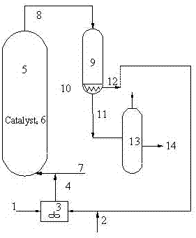
[0034] This example is an ebullating bed hydrogenation test using a hydrocracking catalyst and a powdered hydrorefining catalyst. See attached for specific operation procedure figure 1 . The volume ratio of the powdery hydrofinishing catalyst to the hydrocracking catalyst in Example 1 is 1:3, and the volume ratio of the powdery hydrofinishing catalyst to the hydrocracking catalyst in Examples 2-3 is 2:1. Fully mix the straight-run diesel oil and the powdered hydrorefining catalyst in the mixer to obtain a uniform feed, and enter the ebullating bed reactor through the delivery pump, and the high-pressure hydrogen enters the ebullating bed reactor from the bottom of the ebullating bed reactor. The ebullating bed reactor of the hydrocracking catalyst keeps the catalyst boiling. Under suitable reaction conditions, it is simultaneously and / or sequentially contacted with the hydrocracking catalyst and the powdered hydrorefining catalyst to carry out the catalytic hydrogenation reac...

Embodiment 4~6

[0047] This example is an ebullating bed hydrogenation test using a hydrodepreciation catalyst, a hydrocracking catalyst and a powdered hydrorefining catalyst. See attached for specific operation procedure figure 1 . In Example 4, the volume ratio of the powdered hydrofinishing catalyst to the hydrodecondensation catalyst and the hydrocracking catalyst is 1:4, and the volume ratio of the hydrodepreciation catalyst to the hydrocracking catalyst is 1:1; Example The volume ratio of the powdered hydrofinishing catalyst to the hydrodepreciation catalyst and the hydrocracking catalyst in 5 is 3:1, and the volume ratio of the hydrodepreciation catalyst to the hydrocracking catalyst is 2:1; in Example 6 The volume ratio of the powdered hydrofinishing catalyst to the hydrodepreciation catalyst and the hydrocracking catalyst is 1:3, and the volume ratio of the hydrodepreciation catalyst to the hydrocracking catalyst is 1:3. Fully mix the straight-run diesel oil and the powdered hydror...


PUM

PropertyMeasurementUnit
particle sizeaaaaaaaaaa

Abstract

The invention discloses a method for producing a jet fuel. The method comprises the following contents: (1) thoroughly mixing straight-run diesel oil feedstock and a powdery hydrofining catalyst in a mixer, so as to obtain mixed feed of the catalyst and stock oil; (2) enabling the mixed feed and hydrogen gas to enter a boiling-bed reactor from the bottom of a hydrocracking catalyst containing reactor, and carrying out a hydrogenation reaction, wherein the hydrogenation reaction comprises a hydrocracking reaction and a hydrofining reaction; (3) discharging a powdery hydrofining catalyst containing reacted material flow from the top of the boiling-bed reactor, enabling the material flow to enter a stable reactor, and carrying out supplementary hydrofining under the conditions of relatively low temperatures and/or high volumetric space velocity; (4) subjecting the material obtained in the step (3) to solid-liquid separation, and enabling a liquid phase to enter a fractionating system, thereby obtaining a high-quality jet fuel product. According to the method, a structure-activity relationship between jet fuel properties and hydrocarbon structure composition is considered fully, more ingredients in the straight-run diesel oil feedstock are converted into the jet fuel through optimizing a catalyst system and optimizing process flows and conditions, and a relatively high jet fuel product yield is kept.

Description

technical field [0001] The invention relates to a production method of jet fuel, in particular to a production method for producing high-quality jet fuel through straight-run diesel hydrocracking by adopting an ebullating bed reactor. Background technique [0002] With the continuous expansion of the international air transport industry, the global demand for jet fuel is increasing year by year, with an annual growth rate of about 5.0%, far higher than the annual growth rate of gasoline and diesel of 1.0% to 1.5%, which has greatly driven the global The demand for high-quality jet fuel products in the oil market has also promoted the rapid development of jet fuel production technology in the oil refining industry. Worldwide, the existing jet fuel production technologies are mainly straight-run jet fuel distillate hydrotreating technology and hydrocracking technology. Compared with diesel or gasoline products, jet fuel products have more advantages in profit, which greatly pr...

Claims


Application Information

Patent Timeline
Patent Type & Authority Applications(China)
IPC IPC(8): C10G67/00
CPCC10G67/00C10G2300/70
Inventor 彭冲曾榕辉刘涛吴子明黄新露方向晨杜艳泽
Owner CHINA PETROLEUM & CHEM CORP
Why Eureka
Try Eureka