Waste heat recovery efficient energy-saving stove system

A high-efficiency, energy-saving, waste heat recovery technology, applied in water heaters/stoves, household stoves, household heating and other directions, can solve the problems of heat energy loss, unfavorable kitchen environment maintenance, large gas consumption, etc., to achieve the effect of improving efficiency

Pending Publication Date: 2017-11-14
HANGZHOU SUPERCONDUCTING TECH CO LTD
View PDF8 Cites 2 Cited by
  • Summary
  • Abstract
  • Description
  • Claims
  • Application Information

AI Technical Summary

Problems solved by technology

However, the temperature of the flame is the highest outside the flame, and the flue gas with a higher temperature after the heat exchange between the flame and the bottom of the pot is directly discharged, and is directly discharged to the outside through the flue without secondary use, and the utilization rate of heat is relatively low. The obvious sign is that the kitchen chefs in the canteen or restaurant in summer are "saunaing" every day
It can be seen that the stove with this structure not only has serious heat loss, but also is not conducive to the maintenance of the kitchen environment.
At the same time, the gas consumption of the cooker with this structure is large, and the combustion efficiency is low when it is directly fed into the air, and the combustion is not sufficient.

Method used


Image

  • Waste heat recovery efficient energy-saving stove system
  • Waste heat recovery efficient energy-saving stove system
  • Waste heat recovery efficient energy-saving stove system

Examples


Embodiment 1

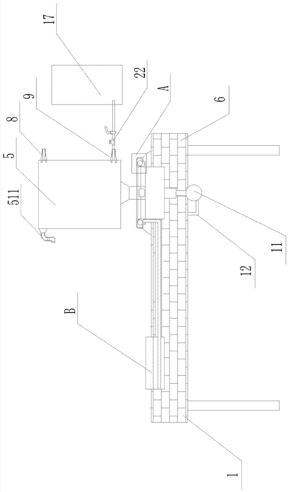
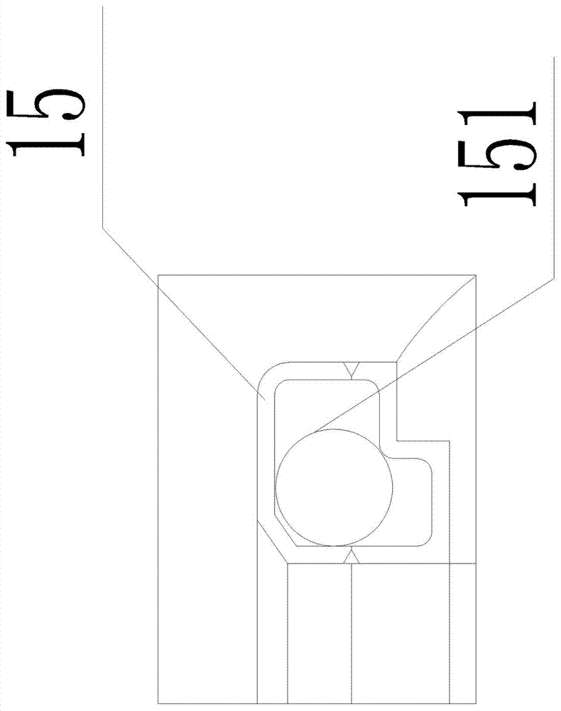
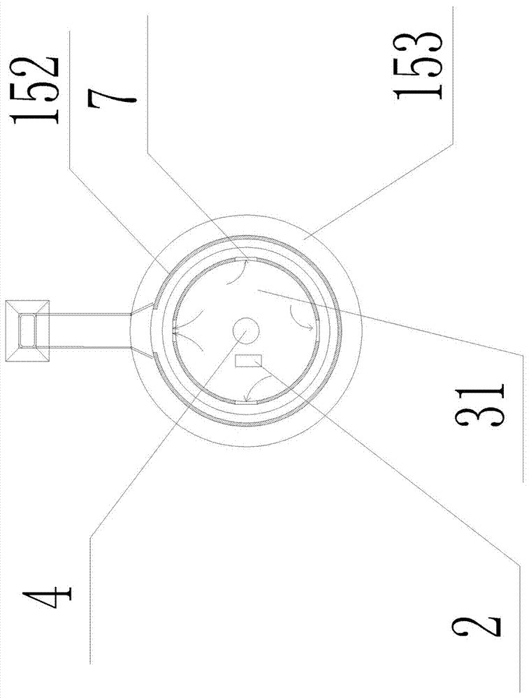
[0040] Such as Figure 1-6As shown, a waste heat recovery high-efficiency energy-saving cooker system includes a cooker body 1. The cooker body 1 includes a bracket 6, a combustion chamber 3, an ignition assembly 4 and a flue gas heat exchange assembly 5. Intake pipe, the combustion chamber 3 is embedded and installed on the bracket 6; the ignition assembly 4 is installed at the bottom of the combustion chamber 3, and the combustion chamber 3 is provided with an air inlet 2, and the air inlet 2 cooperates with the ignition The assembly 4 is set and used to provide oxygen-supplementing air to the ignition assembly 4, and the air inlet 2 is arranged close to the ignition assembly 4; the upper end of the combustion chamber 3 is provided with a vent hole 7, and the vent hole 7 communicates with the flue gas heat exchange assembly 5, and the combustion chamber Hot gas and flue gas pass into the heat exchange component 5;

[0041] The flue gas heat exchange assembly 5 includes a fl...


PUM


Abstract

The invention discloses a waste heat recovery efficient energy-saving stove system. The waste heat recovery efficient energy-saving stove system comprises a stove body. The stove body comprises a support, a combustion chamber, an ignition assembly and a smoke heat exchange assembly. The combustion chamber is mounted on the support in an embedded mode. The ignition assembly is mounted at the bottom of the combustion chamber. The combustion chamber is provided with an air inlet. The air inlet is matched with the ignition assembly and is used for providing oxygenating air for the ignition assembly. Vent holes are formed in the upper end of the combustion chamber and communicate with the smoke heat exchange assembly. The smoke heat exchange assembly comprises a smoke channel and heat conduction pipes, wherein the smoke channel and the heat conduction pipes communicate with the combustion chamber. The smoke channel 51 is arranged longitudinally and transfers heat to the heat conduction pipes. The heat conduction pipe is provided with a longitudinal heat conduction cavity matched with the smoke channel formed longitudinally. A heat conduction medium is introduced from the upper end of the heat conduction cavity and is led out of the lower end of the heat conduction cavity after being heated through the smoke channel from top to bottom. The combustion chamber is provided with a supporting port. The supporting port is used for supporting a cooker or a cover body and sealed with the cooker or the cover body. According to the waste heat recovery efficient energy-saving stove system, the efficient energy-saving stove system is capable of collecting heat energy of the combustion chamber, fully utilizing the heat energy produced by combustion in the combustion chamber and recovering smoke heat.

Description

technical field [0001] The invention relates to an energy-saving kitchen cooker, in particular to a high-efficiency energy-saving cooker system for waste heat recovery. Background technique [0002] Existing stoves are provided with a stove body, a combustion chamber, an air inlet pipe and an air intake pipe connected to the combustion chamber. Air enters the combustion chamber through the air inlet pipe, and gas enters the combustion chamber through the air intake pipe. The system is ignited to generate heat energy, and the flame generated by the combustion contacts the bottom of the pot body to transfer heat to the pot. The cooker with this structure has mature technology and simple structure, so it has been widely used. However, the temperature of the flame is the highest outside the flame, and the flue gas with a higher temperature after the heat exchange between the flame and the bottom of the pot is directly discharged, and is directly discharged to the outside throug...

Claims


Application Information

Patent Timeline
Patent Type & Authority Applications(China)
IPC IPC(8): F24C3/10F24C13/00F24C15/10F24C15/32
CPCF24C3/10F24C13/00F24C15/10F24C15/32Y02B40/00
Inventor 白洪华
Owner HANGZHOU SUPERCONDUCTING TECH CO LTD
Why Eureka
Try Eureka