Diode laser beam collimation method

A technology of diode lasers and laser beams, which is applied in the field of laser technology applications, can solve problems such as inapplicability, difficulty in achieving technical indicators, and inability to simultaneously control the size and divergence angle of emitted light spots, so as to achieve the effect of improving laser power transmission efficiency

Active Publication Date: 2017-11-14
DALIAN UNIV OF TECH
View PDF11 Cites 18 Cited by
  • Summary
  • Abstract
  • Description
  • Claims
  • Application Information

AI Technical Summary

Problems solved by technology

Although this technology can reduce the divergence angle of high-power semiconductor lasers, on the one hand, it is difficult to achieve the technical indicators required by SLidar technology, and on the other hand, it cannot simultaneously control the size of the emission spot and the divergence angle. Therefore, the design of this technology does not Cannot be applied to SLidar technology

Method used


Image

  • Diode laser beam collimation method
  • Diode laser beam collimation method
  • Diode laser beam collimation method

Examples


Embodiment

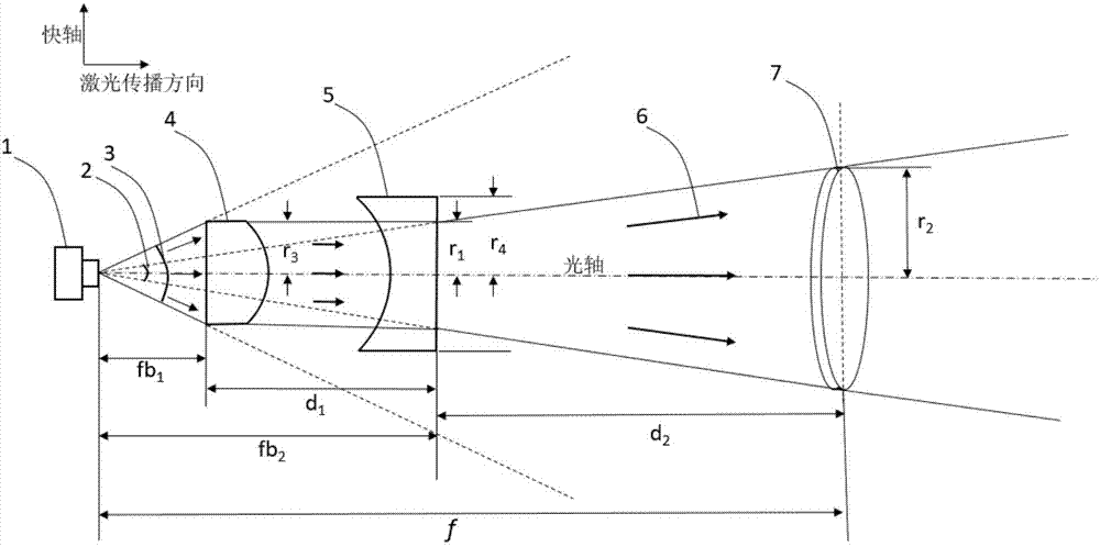
[0022] A. Before adding the shaping device, the divergence angle of the fast axis of the laser beam is 3; after shaping, the divergence angle of the fast axis of the laser beam is 2.

[0023] B. fb 1 Be the distance from the rear plane of the convex cylindrical lens 4 to its focal point, and also the distance from the rear plane of the convex cylindrical lens 4 to the emitting section of the diode laser 1; fb 2 For the distance from the rear plane of the concave cylindrical lens 5 to its focal point, it is also the distance from the plane of the concave cylindrical lens 5 to the emitting section of the diode laser 1; d 1 is the distance from the back plane of the convex cylindrical lens 4 to the back plane of the concave cylindrical lens 5, and the three satisfy fb 2 -fb 1 = d 1 (The position of the focal point defaults to the emission cross section of diode laser 1).

[0024]C and f are the focal length of the convex lens 7, i.e. the distance from the convex lens 7 to the...


PUM


Abstract

The invention belongs to the field of laser technology application, and provides a diode laser beam collimation method. A laser beam emitted by a diode laser is collimated by a convex cylindrical lens, a concave cylindrical lens and a convex lens in turn, and then is emitted into the atmosphere. The laser beam along the fast axis direction firstly passes through the convex cylindrical lens and is collimated into parallel light. Through the concave cylindrical lens, the beam in the fast axis direction is diverged again. The fast axis divergence angle of the output laser beam matches the receiving angle of the convex lens, which greatly improves the coupling efficiency of the fast axis laser beam. The size and divergence angle of a laser beam along the slow axis direction are not changed. The fast axis is placed perpendicular to the Scheimpflug plane. The slow axis is placed parallel to the Scheimpflug plane. Finally, the fast and slow axis laser beams are collimated by the convex lens and emitted into the atmosphere. According to the technical scheme provided by the invention, the coupling efficiency of the emitted light beams is improved under the condition of the same performance of the SLidar system.

Description

technical field [0001] The invention belongs to the technical field of laser technology application and provides a method for collimating a diode laser beam. Background technique [0002] Lidar (Light Detection and Ranging, Lidar) technology is an active optical remote sensing detection technology, which has unique advantages in height / spatial resolution, detection sensitivity, anti-interference ability, and real-time monitoring. Lidar technology has been widely used in monitoring the distribution of atmospheric aerosols, measuring the concentration distribution of atmospheric pollutant gases and greenhouse gases, measuring the temperature field and wind field of the middle and upper atmosphere, and many other aspects. At present, the traditional pulse laser radar is the most widely used at home and abroad. The hardware principle of pulsed lidar technology is to emit nanosecond-scale pulsed light into the atmosphere and detect the intensity of its backscattered light in a t...

Claims


Application Information

Patent Timeline
Patent Type & Authority Applications(China)
IPC IPC(8): G02B27/30G02B27/09
CPCG02B27/0916G02B27/0966G02B27/30Y02A90/10
Inventor 梅亮孔政
Owner DALIAN UNIV OF TECH
Why Eureka
Try Eureka