Check patentability & draft patents in minutes with Patsnap Eureka AI!

Portable visibility transmissometer

A technology of visibility and transmissometer, applied in the direction of transmittance measurement, etc., can solve the problems of increasing difficulty of optical path alignment, occupying land resources, immovability, etc., to avoid interference of background light, small size, coherence and collimation Sex-enhancing effects

Pending Publication Date: 2017-11-17
ANHUI ATMOSPHERE DETECTION TECHN GUARANTEE CENT
View PDF5 Cites 4 Cited by
  • Summary
  • Abstract
  • Description
  • Claims
  • Application Information

AI Technical Summary

Problems solved by technology

Although this atmospheric transmission type visibility meter has high measurement accuracy, it also has shortcomings. First, in order to ensure the accuracy of measurement, the installation baseline between the light transmitting antenna and the light receiving antenna must be greater than 30 meters. Some even need hundreds of meters. Such a long installation baseline not only occupies land resources, but also greatly increases the difficulty of optical path alignment. As a result, it is currently only used in airports and other places that require high visibility measurement accuracy; secondly, it cannot be moved. The transmitter and receiver of the instrument must be installed on a huge base. Once installed, it is not easy to move, so that it can only measure the visibility at a fixed point; finally, after installation or maintenance, it needs to be compensated and calibrated. Optical path alignment calibration, increasing the cost of installation and use

Method used


Image

  • Portable visibility transmissometer

Examples


Embodiment Construction

[0020] The preferred modes of the present invention will be further described in detail below in conjunction with the accompanying drawings.

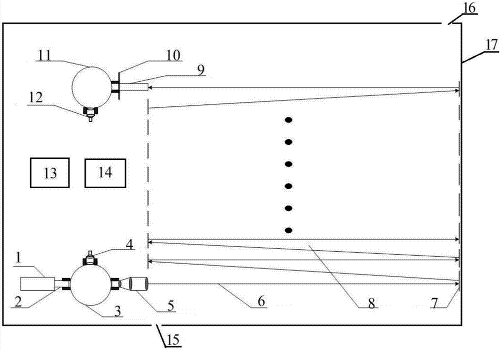
[0021] see figure 1 , the composition of the portable visibility transmissometer is as follows:

[0022] The present invention includes a box body 17, a light source and an optical antenna on its optical path, and a measurement and control component 13 electrically connected to the light source and the optical antenna, wherein:

[0023] The casing 17 is closed, and the closed casing 17 is provided with an air inlet 15 and an air outlet 16 , wherein the air inlet 15 (or the air outlet 16 ) communicates with the air pump 14 .

[0024] The light source is a laser 1 that outputs visible light, and its output wavelength is 525 nm.

[0025] The optical antenna is placed inside the box 17 . The optical antenna in the box body 17 is a light intensity detection integrating sphere 3, a collimating mirror group 5, a reflector 7 positioned at bo...


PUM


Abstract

The invention discloses a portable visibility transmissometer. An air inlet (15) or air outlet (16) communicated with an air pump (14) is formed in a closed box body (17) of the portable visibility transmissometer; a light source is a laser (1) outputting visible lights; an optical antenna located in the box body (17) comprises a light intensity detection integrating sphere (3), a collimating lens set (5), reflecting mirrors (7), a light filter (10) and a light intensity receiving integrating sphere (11) which are sequentially arranged on a light source light path, wherein the reflecting mirrors (7) are arranged at the two ends of a light path reflecting region (8), and a light intensity detector (4) and a photoelectric detector (12) are respectively arranged on the inner walls of the two integrating sphere balls; and a measurement and control component (13) is composed of a computer and a control and acquisition module which are respectively and electrically connected with the air pump (14), the laser (1), the light intensity detectors (4) and the photoelectric detectors (12). The portable visibility transmissometer is small in size, portable and easy to use and maintain and can be widely applied to accurate measurement of atmospheric visibility.

Description

technical field [0001] The invention relates to a visibility transmissometer, in particular to a portable visibility transmissometer. Background technique [0002] Atmospheric visibility is initially defined by the estimated distance of human visual observation as a meteorological parameter, which is an intuitive expression of the scattering and absorption of light by molecules and particles in the atmosphere. Visibility is defined as Meteorological Optical Range (MOR) in meteorology. At first, it was mainly based on manual observation. With the development of photoelectric technology, it has gradually evolved into automatic photoelectric measurement equipment. At present, it is the most commonly used atmospheric visibility measurement instrument in meteorological and transportation departments. It is a forward scatter visibility meter and a transmission visibility meter. The forward scatter visibility meter is designed according to the principle of light scattering, fixed ...

Claims


Application Information

Patent Timeline
Patent Type & Authority Applications(China)
IPC IPC(8): G01N21/59
CPCG01N21/59
Inventor 张世国方海涛汪玮刘振王敏王毛翠
Owner ANHUI ATMOSPHERE DETECTION TECHN GUARANTEE CENT
Features
  • R&D
  • Intellectual Property
  • Life Sciences
  • Materials
  • Tech Scout
  • Unparalleled Data Quality
  • Higher Quality Content
  • 60% Fewer Hallucinations
Learn More