
Left-handed materials based on horn-like basic unit structure

A basic unit and left-handed material technology, applied in electrical components, antennas, etc., can solve the problems of lack of application flexibility and diversity, low practical value, and many adjustment restrictions, and achieve compact structure, simple structure, and high capacitance effect Effect

Active Publication Date: 2020-01-14
XIAMEN UNIV
View PDF7 Cites 0 Cited by
  • Summary
  • Abstract
  • Description
  • Claims
  • Application Information

AI Technical Summary

Problems solved by technology

These structures are usually more complex, and there are many adjustment restrictions, lack of flexibility and diversity of application, so the practical value is not high

Method used


Image

  • Left-handed materials based on horn-like basic unit structure
  • Left-handed materials based on horn-like basic unit structure
  • Left-handed materials based on horn-like basic unit structure

Examples


Embodiment 1

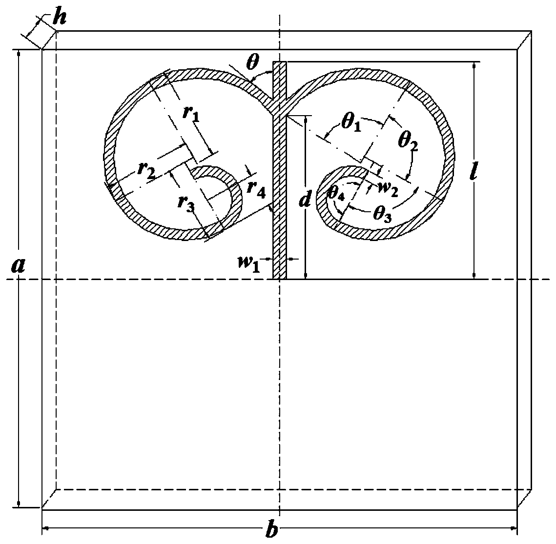
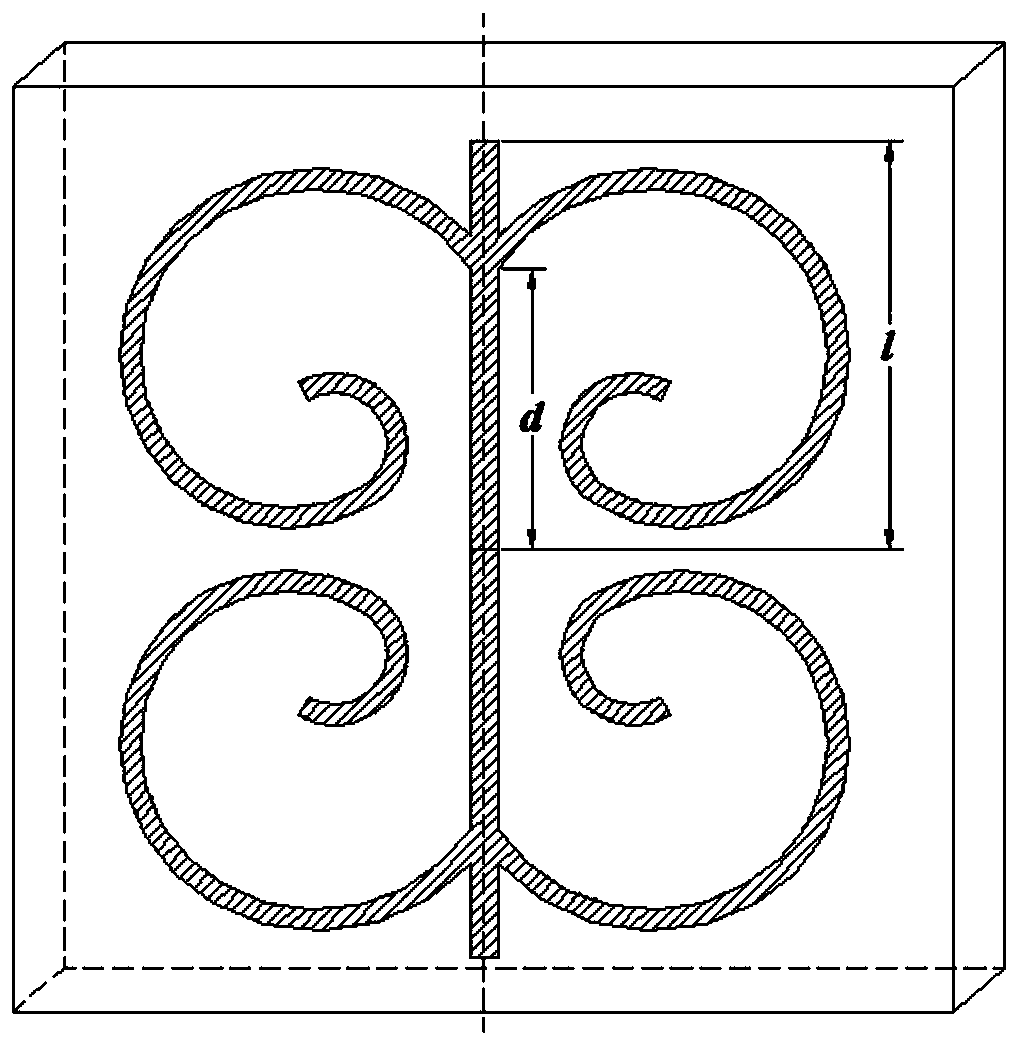
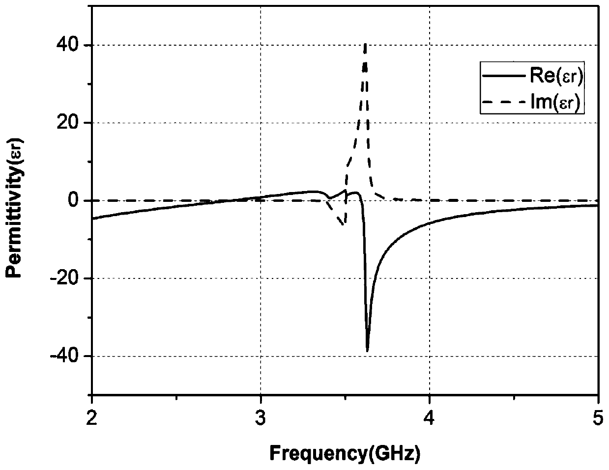
[0035] Embodiment 1: see figure 2 , parameterized with figure 1 same. In this embodiment, n=2, that is, figure 1 The claw-like structure of the Zhongliang conductor layer is copied into two parts, and they are rotated 180° with the midpoint of the bottom edge of the metal rod as the center of the circle, forming a two-piece petal-shaped left-handed material. The length of the metal rod is l=6mm and the width is w 1 = 0.4 mm. The distance from the connection point between the arc-shaped recursive spiral structure and the metal rod to the bottom edge of the metal rod is d=4.0mm. The angle between the tangent line at the starting point of the spiral structure and the metal rod is θ=30°, and the radii of the 4 arcs of the spiral structure are r 1 = 3mm, r 2 = 2.7 mm, r 3 = 2.4mm, r 4 =1.05mm, the width is w 2 = 0.3mm. Depend on image 3 , 4 It can be seen that the equivalent dielectric constant is negative in the 2.00-2.82GHz and 3.60-5.00GHz frequency bands, the equi...

Embodiment 2

[0036] Example 2: see Figure 6 , parameterized with figure 1 same. In this embodiment, n=6, that is, figure 1 The croissant structure of the Zhongliang conductor layer is copied into 6 parts, and they are rotated 60° with the midpoint of the bottom edge of the metal rod as the center of the circle, forming a six-piece petal-shaped left-handed material. The length of the metal rod is l=5mm and the width is w 1 = 0.3 mm. The distance from the connection point between the arc-shaped recursive spiral structure and the metal rod to the bottom edge of the metal rod is d=3.7mm. The angle between the tangent line at the starting point of the spiral structure and the metal rod is θ=10°, and the radii of the 4 arcs of the spiral structure are r 1 = 1.06mm, r 2 = 0.91 mm, r 3 = 0.76mm, r 4 =0.305mm, width is w 2 = 0.15 mm. Depend on Figure 7-9 It can be seen that the real part of the equivalent permittivity of the structure in the simulation frequency range is below 0, that ...


PUM


Abstract

The invention discloses a left-handed material based on a cavel-shaped basic unit structure, and relates to the left-handed material. The left-handed material is provided with a dielectric substrate; the upper surface of the dielectric substrate is covered with a metal good conductor layer; the cavel-shaped basic unit structure consists of two symmetrical circular arc-shaped recursive helical structures etched in the two sides of a midperpendicular of the good conductor layer and a linear metal rod in the center and connected therewith; and the midpoint of the bottom edge of the metal rod coincides with the center of the dielectric substrate. The circular arc-shaped recursive helical structure is obtained by connection of multiple sections of circular arcs in a tangential manner in sequence based on radiuses from big to small and field angles of certain sizes; and an included angle is formed between the tangent line on the starting point of the helical structure and the metal rod. The cavel-shaped structure of the good conductor layer is copied into n parts, and is rotated for 360 degree / n by taking the midpoint of the bottom edge of the metal rod as the centre of a circle to be placed, so that the petal-shaped left-handed material can be further formed.

Description

technical field [0001] The present invention relates to left-handed materials, in particular to left-handed materials based on horn-like basic unit structure. Background technique [0002] Left-Handed Material, also known as Negative Index Material and Double Negative Material [1], is an artificial periodic structure that does not exist in nature. Compared with right-handed materials, the permittivity and magnetic permeability of left-handed materials are negative, the electric field, magnetic field and wave vector follow the left-handed spiral rule, and the energy propagation direction of electromagnetic waves is opposite to the wave vector direction. Therefore, compared with ordinary materials in nature, left-handed materials have many strange electromagnetic properties, such as negative refraction, inverse Doppler effect, inverse Cherenkov effect, perfect lens effect, etc. This idea was first proposed by former Soviet physicist V.G. Veselago in 1967 [2]. In 1999, Pendry...

Claims


Application Information

Patent Timeline
Patent Type & Authority Patents(China)
IPC IPC(8): H01Q15/00
CPCH01Q15/0086
Inventor 游佰强黄涛周建华戚宇轩李伟文
Owner XIAMEN UNIV
Learn More