
Full-automatic machining device for rotary table of bearing seat

A technology of processing device and bearing seat, applied in the field of workpiece processing and manufacturing, can solve problems such as affecting the service life of bearings, increasing production costs of enterprises, affecting product quality, etc.

Active Publication Date: 2017-11-21
泉州安肯自动化机械有限公司
View PDF15 Cites 6 Cited by
  • Summary
  • Abstract
  • Description
  • Claims
  • Application Information

AI Technical Summary

Problems solved by technology

In the prior art, many stations need to be processed during the processing of the bearing seat turntable. For example, the four positioning holes need to be drilled, chamfered and other processes, and the processing of the middle bearing hole requires multiple processing. Therefore, the entire bearing The turntable needs to be processed on different machine tools, that is, after the processing is completed on one machine tool, the workpiece needs to be disassembled and then transferred to another machine tool for clamping and positioning. Moving not only increases the workload but also reduces the processing efficiency, and the labor intensity of the workers is high. At the same time, because each clamping and positioning cannot be guaranteed to be exactly the same, it also affects the processing accuracy of the bearing seat turntable, thereby affecting the quality of the product. Make it affect the service life of the whole bearing when it is used with the shaft
At the same time, due to the many processing procedures of the existing bearing seat turntable, there are many processing equipments, and the overall space occupied by the production equipment is large, which increases the production cost of the enterprise.

Method used


Image

  • Full-automatic machining device for rotary table of bearing seat
  • Full-automatic machining device for rotary table of bearing seat

Examples


Embodiment Construction

[0012] The present invention will be further described in conjunction with the accompanying drawings and specific embodiments.

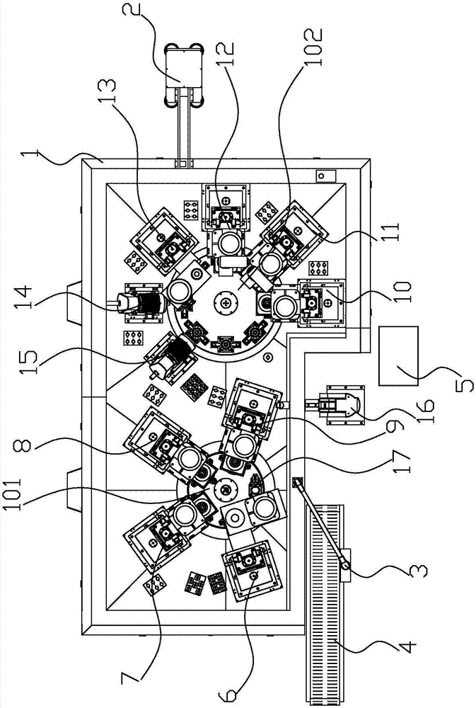
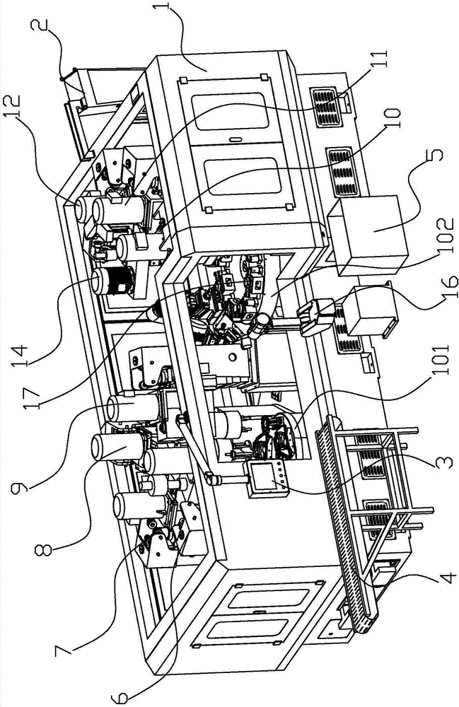
[0013] refer to figure 1 and figure 2 , the preferred full-automatic processing device for the bearing seat turntable of the present invention includes a frame 1, a PLC controller 2, a control panel 3, a feeding and conveying mechanism 4, an unloading box 5, an end surface roughing mechanism 6, and the outer circle of the bearing hole is rough. Car mechanism 7, multi-axis device drilling mechanism 8, multi-axis device chamfering mechanism 9, rough reaming inner hole mechanism 10, rough boring inner hole mechanism 11, fine boring inner hole mechanism 12, inner hole oil groove boring mechanism 13, oil injection Hole drilling mechanism 14, oil hole tapping mechanism 15 and robot 16, the left and right parts of the frame 1 are respectively provided with a first rotary table 101 that rotates clockwise and a second rotary table that rotates counterclockw...


PUM


Abstract

The invention relates to the field of workpiece machining and provides a full-automatic machining device for a rotary table of a bearing seat. The full-automatic machining device comprises a rack, a PLC (Programmable Logic Controller), a feeding conveying mechanism, an unloading box, an end face rough turning mechanism, a bearing hole top circle rough turning mechanism, a multi-spindle tool drilling mechanism, a multi-spindle tool chamfering mechanism, a rough reaming inner hole mechanism, a rough boring inner hole mechanism, a fine boring inner hole mechanism, an inner hole oil groove boring mechanism, an oil injection hole drilling mechanism, an oil injection hole tapping mechanism and a robot, wherein driving units of the feeding conveying mechanism, a first rotary worktable, a second rotary worktable, each clamping mechanism, the end face rough turning mechanism, the bearing hole top circle rough turning mechanism, the multi-spindle tool drilling mechanism, the multi-spindle tool chamfering mechanism, the rough reaming inner hole mechanism, the rough boring inner hole mechanism, the fine boring inner hole mechanism, the inner hole oil groove boring mechanism, the oil injection hole drilling mechanism, the oil injection hole tapping mechanism and the robot are connected and controlled by the PLC. By adopting the full-automatic machining device provided by the invention, the problems that the number of times of machining the rotary table of the bearing seat is more and the production cost is high are solved.

Description

technical field [0001] The invention relates to the field of workpiece processing and manufacturing, in particular to a fully automatic processing device for a bearing seat turntable. Background technique [0002] At present, the bearing seat in the prior art is widely used in rotating equipment as a supporting member of the bearing. The bearing seat is provided with concentric circular holes, and the concentric circular holes are the installation stations of the bearings. In the prior art, in rotating equipment requiring high rotation precision, heavy load or high speed, it is often necessary to install two or more bearings in the same bearing seat to provide two or more support points for the rotating shaft. Such as the screw pump bearing box with a long drive shaft, the fan spindle bearing box of a large cooling tower, etc. In the prior art, many stations need to be processed during the processing of the bearing seat turntable. For example, the four positioning holes ne...

Claims


Application Information

Patent Timeline
IPC IPC(8): B23P23/02
CPCB23P23/02Y02P70/10
Inventor 苏立团戴培海陈建团林世栋李永富
Owner 泉州安肯自动化机械有限公司
Learn More