Temperature adjustment system of RTO oxidizing furnace, and adjustment technology thereof
A technology of temperature regulation and oxidation furnace, applied in incinerators, combustion methods, lighting and heating equipment, etc., can solve the problems of delayed combustion of VOCs, large pipe size, easy damage, etc., and achieve the effect of ensuring normal operation
- Summary
- Abstract
- Description
- Claims
- Application Information
AI Technical Summary
Problems solved by technology
Method used
Image

Examples
Embodiment 1
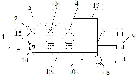
[0029] like figure 1 As shown, the exhaust gas enters the regenerator A through the exhaust gas pipeline 1, and after being heated by the high-temperature regenerator, it enters the oxidation chamber 5 for combustion, and the high-temperature purified gas after combustion enters the regenerator B to heat the regenerator and cool down The final purified gas passes through the purified gas pipeline 10, and is discharged to the chimney 9 through the induced draft fan 8. Part of the flue gas passes through the purge pipeline 12 and enters the regenerator C where the waste gas is fed in the previous stage, blowing the residual waste gas into the oxidation chamber 5 for combustion. When the oxidation chamber 5 is overheated, the regulating valve 7 is opened, and the low-temperature purified gas is introduced into the oxidation chamber 5, and the temperature of the oxidation chamber 5 is lowered to the normal operating temperature.
Embodiment 2
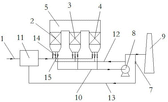
[0031] like figure 2 As shown, the exhaust gas enters the regenerator A through the exhaust gas pipeline 1, and after being heated by the high-temperature regenerator, it enters the oxidation chamber 5 for combustion, and the high-temperature purified gas after combustion enters the regenerator B to heat the regenerator and cool down The final purified gas passes through the purified gas pipeline 11, and is discharged to the chimney 9 through the induced draft fan 10. Part of the flue gas passes through the purge pipeline 7, enters the regenerator C where the waste gas is fed in the previous stage, and blows the residual waste gas into the oxidation chamber 5 for combustion. When the oxidation chamber 5 is overheated, the regulating valve 7 is opened, and the low-temperature purified gas enters the gas mixing device 11 to mix with the exhaust gas to reduce the concentration of VOCs in the exhaust gas, thereby reducing the temperature of the oxidation chamber 5 to the normal o...
Embodiment 3
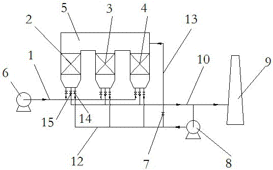
[0033] like image 3 As shown, the exhaust gas enters the regenerator A from the blower 6 through the exhaust gas pipeline 1. After being heated by the high-temperature regenerator, it enters the oxidation chamber 5 for combustion, and the high-temperature purified gas after combustion enters the regenerator B to heat the heat storage. body, the purified gas after cooling is discharged to the chimney 9 through the purified gas pipeline 10. Part of the flue gas is passed through the blowing pipeline 12 by the induced draft fan 8, and enters the regenerator C where the waste gas is fed in the previous stage, and the residual waste gas is blown into the oxidation chamber 5 for combustion. When the oxidation chamber 5 is overheated, the regulating valve 7 is opened, and part of the low-temperature purified gas enters the oxidation chamber 5 by the induced draft fan 8, and the temperature of the oxidation chamber 5 is lowered to the normal operating temperature.
PUM
 Abstract
Description
Claims
Application Information
 - R&D
- Intellectual Property
- Life Sciences
- Materials
- Tech Scout
- Unparalleled Data Quality
- Higher Quality Content
- 60% Fewer Hallucinations
Browse by: Latest US Patents, China's latest patents, Technical Efficacy Thesaurus, Application Domain, Technology Topic, Popular Technical Reports.
© 2025 PatSnap. All rights reserved.Legal|Privacy policy|Modern Slavery Act Transparency Statement|Sitemap|About US| Contact US: help@patsnap.com