
Recycling system for exhaust waste heat of shower room

A waste heat recovery system and waste heat recovery technology, applied in the field of exhaust systems, can solve problems such as difficult temperature control, water vapor retention, and complex exhaust air components, and achieve high energy utilization, reduce energy waste, and avoid heat loss.

Pending Publication Date: 2017-11-21
SHENYANG JIANZHU UNIVERSITY
View PDF8 Cites 5 Cited by
  • Summary
  • Abstract
  • Description
  • Claims
  • Application Information

AI Technical Summary

Problems solved by technology

[0003] Compared with the indoor environment of ordinary buildings, the indoor environment of large bathrooms is a high-temperature and high-humidity environment. During operation, a large amount of water vapor will be generated. The air to be discharged has the characteristics of high humidity and high temperature. The composition of the discharged air that requires waste heat recovery is complex. Therefore, the gas must be treated before waste heat recovery. Filtration and dehumidification has become the key to air treatment. If the indoor exhaust air volume is small, the indoor temperature comfort will be guaranteed, but it will cause water vapor retention in the bathroom, excessive humidity, and difficult temperature control. , the indoor air quality is poor; the exhaust air volume is large, the fresh air volume is increased, and the indoor air quality is improved, but the air velocity is high, which will entrain more indoor heat and discharge it, reducing the temperature in the bathroom or increasing the energy consumption of heating equipment
At the same time, the loss of heat is not good for maintaining the water supply temperature of the facilities in the bathroom, and will increase the energy consumption of the boiler room (water heater)

Method used


Image

  • Recycling system for exhaust waste heat of shower room

Examples


Embodiment Construction

[0016] The technical solutions provided by the present invention will be described in detail below in conjunction with specific examples. It should be understood that the following specific embodiments are only used to illustrate the present invention and are not intended to limit the scope of the present invention.

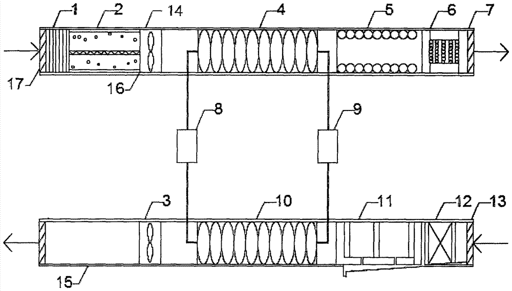
[0017] This embodiment provides a bathroom exhaust waste heat recovery system, see figure 1 , comprising an exhaust system, an air inlet duct 16 and a waste heat recovery system, the exhaust system comprising an exhaust duct 15, a first fan 3, a first rough filter 12 and a membrane separator 11, and the waste heat recovery system comprising Compressor 8, evaporator 10, condenser 4 and expansion valve 9, described condenser 4 is arranged in the air inlet pipe 16; Sequentially pass through the first rough filter 12, membrane separator 11 and evaporator 10; the evaporator 10 is connected with the inlet of the compressor 8, and the outlet of the compressor 8 is conne...


PUM


Abstract

The invention provides a recycling system for exhaust waste heat of a shower room. The system comprises an exhaust system, an air inlet pipeline and a waste heat recovery system. The exhaust system comprises an exhaust pipeline, a first fan, a first low efficient filter and a membrane separator. The waste heat recovery system comprises a compressor, an evaporator, a condenser and an expansion valve, and the condenser is arranged in the air inlet pipeline; air exhausted in shower room from the first fan successively passes through the first low efficient filter, the membrane separator and the evaporator through the exhaust port of the exhaust pipeline; the evaporator is connected to the inlet of the compressor, the outlet of the compressor is connected to the condenser, and the condenser is connected to the evaporator through the expansion valve. According to the recycling system for exhaust waste heat of the shower room provided by the invention, high humidity air exhausted from the shower room is initially filtered and dehumidified and the humidity of gas is reduced, so that the waste heat recovery standard is met. The waste heat in exhaust of the shower room is effectively recovered and utilized for pre-heating fresh air in the shower room, so that the energy consumption is reduced and the energy resource is saved.

Description

technical field [0001] The invention relates to an exhaust system, in particular to a bathroom exhaust waste heat recycling system. Background technique [0002] As the world pays more and more attention to building energy conservation and the world oil crisis continues to emerge, waste heat recovery has become a new direction of energy conservation research. A good waste heat recovery system can re-collect and utilize waste heat and waste heat. As we all know, the indoor environment of the bathroom is very complicated, and high humidity and high temperature become its main characteristics. Controlling the indoor environment of the bathroom to ensure the comfort of the indoor personnel is an important part of the bathroom. [0003] Compared with the indoor environment of ordinary buildings, the indoor environment of large bathrooms is a high-temperature and high-humidity environment. During operation, a large amount of water vapor will be generated. The air to be discharged ...

Claims


Application Information

Patent Timeline
IPC IPC(8): F24F3/16F24F12/00F24F13/28
CPCF24F3/16F24F12/001F24F13/28F24F8/22F24F8/30F24F8/192F24F8/10Y02P80/15
Inventor 于水邵一飞冯国会
Owner SHENYANG JIANZHU UNIVERSITY
Features
  • Generate Ideas
  • Intellectual Property
  • Life Sciences
  • Materials
  • Tech Scout
  • Unparalleled Data Quality
  • Higher Quality Content
  • 60% Fewer Hallucinations
Learn More