Supercharge Your Innovation With Domain-Expert AI Agents!

Sectional sludge drying system

A sludge drying and segmented technology, applied in sludge treatment, pyrolysis sludge, water/sludge/sewage treatment, etc., can solve the problems of low drying efficiency, poor economy, secondary pollution, etc. , to achieve the effect of recycling, increasing the total surface area, and high drying efficiency

Pending Publication Date: 2017-11-24
广东省绿革环保科技有限公司
View PDF7 Cites 2 Cited by
  • Summary
  • Abstract
  • Description
  • Claims
  • Application Information

AI Technical Summary

Problems solved by technology

[0004] Traditional sludge treatment includes incineration, landfill, composting, etc. Incineration is not economical due to the high moisture content of sludge and is prone to produce dioxins and other substances. Landfilling occupies land and is likely to cause secondary pollution. The sludge contains heavy metals Not suitable for direct composting
[0005] Therefore, in the prior art, the drying equipment is generally used to remove the moisture in the sludge, specifically, the drying wind is blown to the surface of the sludge to accelerate the air flow on the surface of the sludge, so that the moisture of the sludge can be evaporated, but on the one hand, In the process of drying air generation, the fresh air comes from the outside, and the humid cold air obtained after drying is directly discharged, which is not conducive to energy conservation and environmental protection, and does not realize gas circulation. Second, relying solely on the method of accelerating air flow on the sludge surface is harmful to sludge Drying, drying efficiency is low
In the third aspect, more than one method is used for drying, which is not conducive to energy saving and environmental protection

Method used


Image

  • Sectional sludge drying system
  • Sectional sludge drying system
  • Sectional sludge drying system

Examples


Embodiment Construction

[0033] The present invention will be further described below in conjunction with the accompanying drawings.

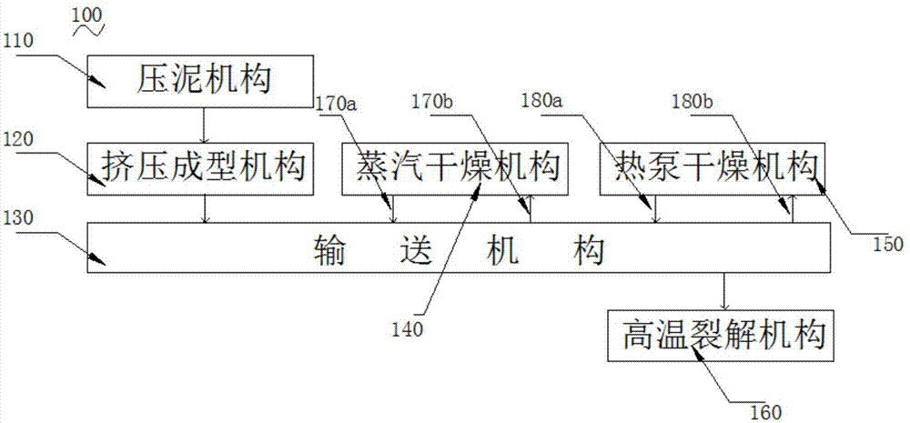
[0034] like figure 1 Shown is the structural principle diagram of the present invention.

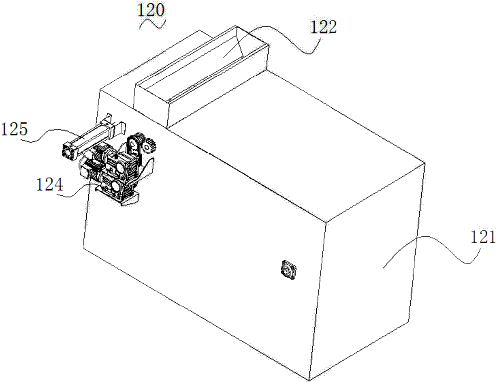
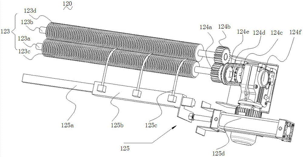
[0035] The segmented sludge drying system 100 includes a mud pressing mechanism 110 for dewatering the sludge, and an extrusion molding machine for extruding the dehydrated block or powder or sludge sludge into strip sludge. Mechanism 120, conveying mechanism 130 for transporting sludge, steam drying mechanism 140 for primary drying of sludge, heat pump drying mechanism 150 for secondary drying of sludge, high temperature pyrolysis of sludge The pyrolysis mechanism 160. The extrusion forming mechanism 120 is located below the mud pressing mechanism 110, the conveying mechanism 130 is located below the extruding forming mechanism 120, the steam drying mechanism 140 and the heat pump drying mechanism 150, and the conveying mechanism 130 passes through the first air inlet pipe 170...


PUM


Abstract

The invention relates to the field of sludge treatment, and particularly relates to a sectional sludge drying system. The sectional sludge drying system comprises a sludge pressing mechanism for dewatering sludge, an extrusion forming mechanism, a transport mechanism, a steam drying mechanism for primarily drying the sludge, a heat pump drying mechanism for secondarily drying the sludge, and a high-temperature pyrolyzing mechanism for pyrolyzing the sludge at a high temperature; and the extrusion forming mechanism is disposed below the sludge pressing mechanism, the transport mechanism is disposed below the extrusion forming mechanism, the steam drying mechanism and the heat pump drying mechanism, the transport mechanism is connected with the steam drying mechanism by virtue of a first gas inlet pipeline and a first gas outlet pipeline, the transport mechanism is connected with the heat pump drying mechanism by virtue of a second gas inlet pipeline and a second gas outlet pipeline, and one end, away from the extrusion forming mechanism, of the transport mechanism is connected with the high-temperature pyrolyzing mechanism. The sectional sludge drying system is energy-saving, environmentally friendly, capable of circularly supplying the gas, capable of treating the sludge by virtue of dry hot air, and high in drying efficiency.

Description

technical field [0001] The invention relates to the field of sludge treatment, in particular to a segmented sludge drying system. Background technique [0002] With the improvement of China's urbanization level, the amount of urban sewage treatment is increasing, and the amount of sludge that needs to be safely treated is increasing day by day. As of the end of March 2014, a total of 3,622 sewage treatment plants have been built in cities and towns in my country, with a sewage treatment capacity of about 153 million m3 / d, and the output of sludge with a moisture content of 80% has exceeded 30 million tons; in 2015, my country's annual sludge output (80 % water content) reached 33.59 million tons; it is estimated that by 2018, the sludge output with 80% water content will further exceed 40 million tons. [0003] As a follow-up product of sewage treatment, sludge is actually the concentration of pollutants in sewage. It has the characteristics of high water content, complex co...

Claims


Application Information

Patent Timeline
IPC IPC(8): C02F11/12C02F11/10
CPCC02F11/10C02F11/122
Inventor 乐恒香谢丁中
Owner 广东省绿革环保科技有限公司
Features
  • R&D
  • Intellectual Property
  • Life Sciences
  • Materials
  • Tech Scout
  • Unparalleled Data Quality
  • Higher Quality Content
  • 60% Fewer Hallucinations
Learn More