Inner drilling machine and construction method thereof

A construction method and drilling rig technology, which are applied to drilling equipment and methods, rotary drilling rigs, drill pipes, etc. The problem of large loss of bearing capacity, etc., achieves the effect of simple structure, light weight and lower project cost.

Active Publication Date: 2017-11-24
JIANHUA CONSTR MATERIALS (JIANGSU) CO LTD
View PDF10 Cites 7 Cited by
  • Summary
  • Abstract
  • Description
  • Claims
  • Application Information

AI Technical Summary

Problems solved by technology

This high-pressure rotary spraying (without drill pipe) drilling method into the rock construction method destroys the structure of the original pile tip soil and causes a large loss of bearing capacity at the pile tip
[0004] Patent application "Static pressure pile sinking construction technology with alternating segmented and progressive static pressure pile driving holes and static pressure pile driving" (CN200910186602.X), patent application "A kind of static pressure mid-digging pile driving machine and static pressure mid-digging pile construction "Method" (CN201010278241.4) and the patented "Introduced Hole Static Pile Machine" (CN201220548408.9) both install a fixed frame on the existing static press, and advance the construction of the introductory hole through hydraulic expansion and contraction. The construction operation of piles and piles belongs to the one-piece or integral pile driver, which affects the original structure of the pile driver and the later use. It is easy to collapse the hole during construction, and it is impossible to achieve simultaneous drilling and pile pressing. and without gas injection construction, a larger power unit needs to be installed, the construction efficiency is low, and the bearing capacity of the pile tip and the quality of the pile sinking cannot be guaranteed

Method used


Image

  • Inner drilling machine and construction method thereof
  • Inner drilling machine and construction method thereof
  • Inner drilling machine and construction method thereof

Examples


Embodiment Construction

[0034] It should be noted that, in the case of no conflict, the embodiments in the present application and the features in the embodiments can be combined with each other. The present invention will be described in detail below with reference to the accompanying drawings and examples.

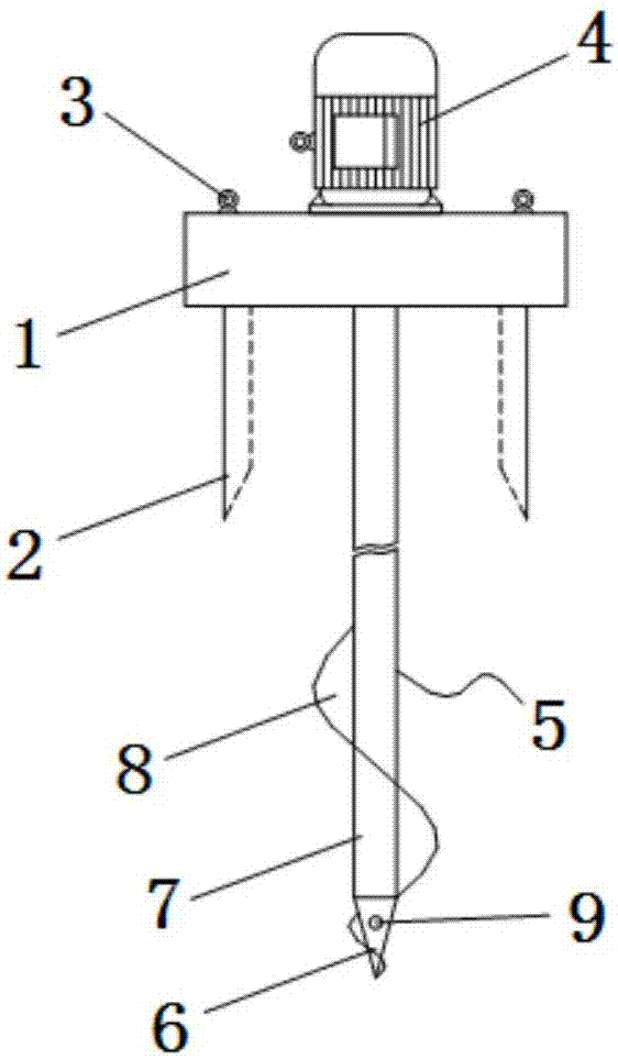
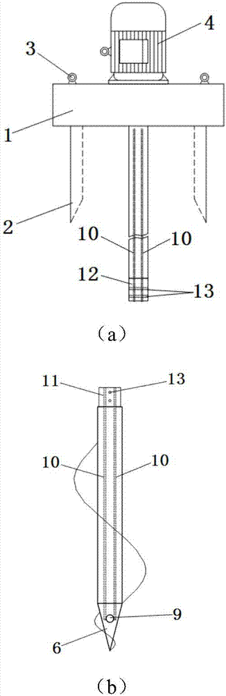
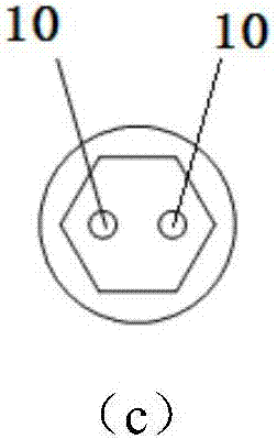
[0035] A kind of internal drilling machine of the present embodiment mainly comprises drilling machine 14 and control system 16, and drilling machine 14 comprises speed reducer 1, fixture 2, lug 3, driving device and drilling tool 5, and drilling tool 5 comprises drill bit 6, drill rod 7. Spiral blade 8 and drill pipe joint. Wherein, the clamp 2 and the drill pipe 7 are arranged below the reducer 1 , and the lifting lug 3 is arranged above the reducer 1 . The drive device is connected to the control system 16, wherein the drive device can be a motor or a hydraulic drive system. In this embodiment, the motor 4 is used as the drive device, and the reducer 1 is connected to the motor 4 . The dri...


PUM


Abstract

The invention discloses an inner drilling machine and a construction method thereof. The inner drilling machine comprises a tunneling and drilling machine; the tunneling and drilling machine comprises a reducer, a fixture, a driving device and a drilling tool; the fixture is arranged on the reducer; a through hole is formed in the drilling tool, and an outlet of the through hole is formed in the bottom of the drilling tool; the drilling tool comprises a drill bit, a drilling rod and a helical blade; the drilling rod is connected with the reducer; the drilling rod is divided into a plurality of sections which are connected through drilling rod joints; and the drilling rod joints adopt male and female joints. According to the inner drilling machine and the construction method thereof, when the inner drilling machine is adopted in construction for precast hollow piles, simultaneous conducting of guiding holes and pressing piles can be achieved without changing original pile machine structure; and the inner drilling machine is low in cost, simple in structure, small in self-weight, convenient to construct, low in noise, low in vibration, friendly in environmental protecting and high in efficiency, and the problem of difficult construction of prefabricated hollow piles in dense sand layer geology can be effectively solved.

Description

technical field [0001] The invention relates to the technical field of building pile foundations, in particular to an internal drilling rig and a construction method thereof. Background technique [0002] With the continuous development of the industry, various high-rise buildings and complex structural forms emerge in an endless stream, and the requirements for pile foundations are getting higher and higher. Various prefabricated hollow piles with new technologies and materials gradually replace the traditional pile foundation forms. Therefore, it has become more and more obvious that in many domestic engineering projects, it is difficult to pass through the thicker dense sand layer geology when using existing construction equipment (such as static pressure equipment, hammering equipment, etc.) when sinking prefabricated hollow piles. During construction, the pile body is damaged or cannot reach the designed pile length, which makes it unable to meet the requirements of the...

Claims


Application Information

Patent Timeline
Patent Type & Authority Applications(China)
IPC IPC(8): E21B7/18E21B3/02E21B17/00
CPCE21B3/02E21B7/18E21B17/00Y02E10/20
Inventor 张雁许俊郭强毛由田陈巧
Owner JIANHUA CONSTR MATERIALS (JIANGSU) CO LTD
Why Eureka
Try Eureka