Quench-type reactor

A reactor and cold-shock technology, which is applied in chemical/physical/physical chemical reactors, chemical instruments and methods, chemical/physical/physical chemical processes, etc., can solve the problem of low conversion rate of raw materials, lower bed temperature, bed Problems such as large layer pressure drop, achieve uniform bed temperature, reduce bed temperature, and reduce bed pressure

Active Publication Date: 2017-11-28
SINOPEC ENG +1
View PDF14 Cites 2 Cited by
  • Summary
  • Abstract
  • Description
  • Claims
  • Application Information

AI Technical Summary

Problems solved by technology

In addition, China CN104818065A can suppress catalyst carbon deposition and reduce bed temperature by passing water vapor into raw material gas, but the disadvantages are large bed pressure drop, low raw material conversion rate, and local "flying temperature" phenomenon is prone to occur

Method used


Image

  • Quench-type reactor
  • Quench-type reactor
  • Quench-type reactor

Examples


Embodiment 1

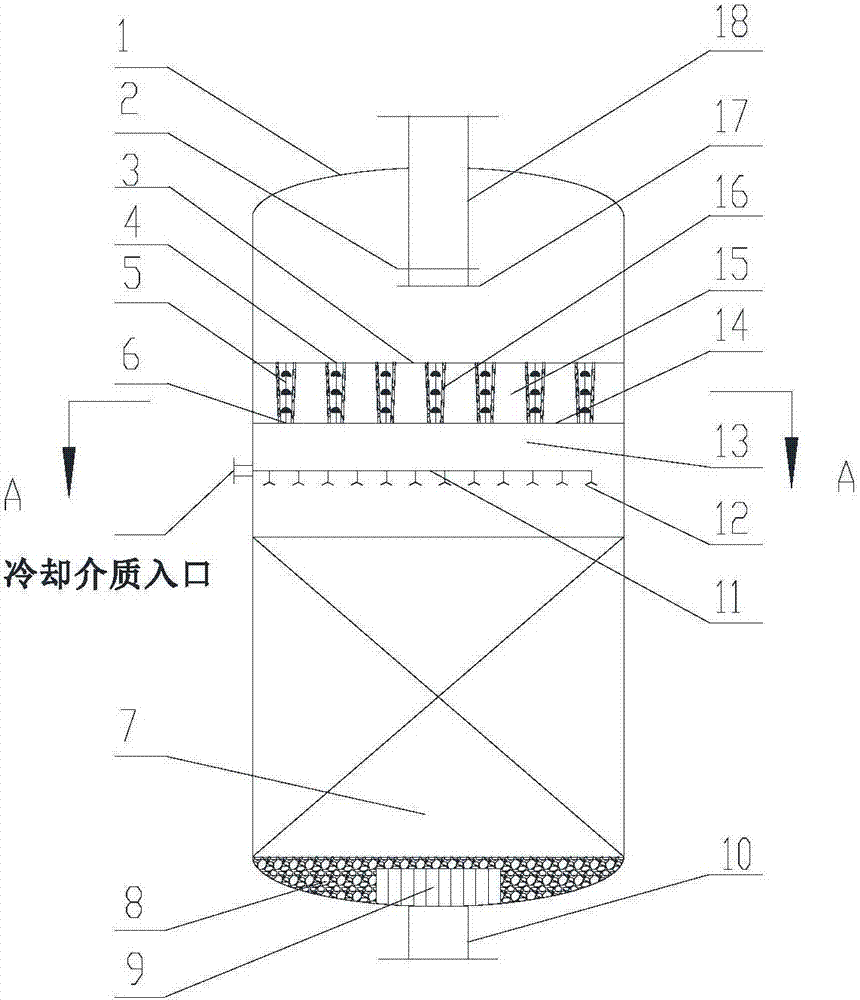
[0068] Such as figure 1As shown, the chilled shock reactor adopted in this embodiment includes a pressure-bearing shell 1 with an inlet pipe 18 at the upper end and an outlet pipe 10 at the lower end. The first gas distributor 2 is provided at the bottom of the inlet pipe 18, and A second gas distributor 17 is arranged below the first gas distributor 2 . The bottom of the inlet pipe 18 has an axial microchannel reaction zone 21 and an axial catalytic reaction zone 7, and the axial microchannel reaction zone 21 is positioned directly above the axial catalytic reaction zone 7, and the axial microchannel reaction zone 21 includes an axial Microchannel reaction unit 15. Axial micro-channel reaction unit 15 is a container that can accommodate micro-reaction channels 16 coaxial with cylindrical housing 1, and includes bottom sealing plate 14, top sealing plate 3 and side walls, and its side walls are in line with the sides of housing 1. The walls are sealed and connected, and the ...

Embodiment 2

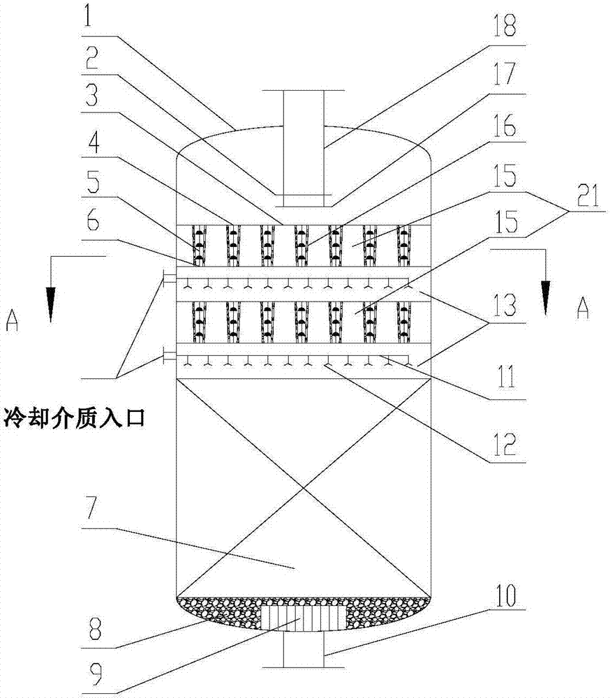
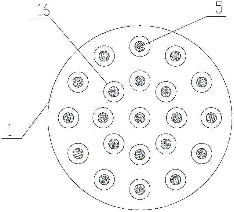
[0075] Such as figure 2 , image 3 As shown, the reactor in this embodiment has the same structure parameters as the reactor in embodiment 1, such as the inner diameter of the shell, the height of the axial catalytic reaction zone and the height of the axial microchannel reaction unit. The difference from Embodiment 1 is that there are two axial microchannel reaction units 15 in this embodiment, and a cooling medium distributor 11 is also arranged in the gap between the two axial microchannel reaction units 15 .

[0076] The reactor proposed by the present invention is applied to the methanation reaction of syngas, and the amount of active metal Ni loaded in the conical tube is 21.6g / m 2 . The synthesis gas enters the reactor from the inlet pipe, and after axially passing through the two columns, the methanation reaction continues in the axial catalytic reaction zone, and the reaction product leaves the reactor through the outlet pipe at the bottom of the reactor.

[0077]...


PUM


Abstract

The invention discloses a quench-type reactor. The reactor comprises a radial cylindrical sealed pressure-bearing shell (1), an air inlet pipe (18), an air outlet pipe (10), as well as an axial micro-channel reaction zone (21) and an axial catalytic reaction zone (7), wherein gaps (13) are formed between the axial micro-channel reaction zone (21) and the axial catalytic reaction zone (7); cooling medium distributors (11) are arranged in the gaps (13); at least one cooling medium inlet is formed in the shell (1) corresponding to the side face of each gap (13); the cooling medium inlets are connected with the cooling medium distributors (11) through cooling medium pipelines. The reactor is small in usage amount of active ingredients of the catalyst, low in pressure drop and low in bed temperature and avoids a 'temperature runaway' phenomenon.

Description

technical field [0001] The invention relates to a cold shock reactor. Background technique [0002] There are mainly two types of fixed bed reactors, one is axial fixed bed reactor and the other is radial fixed bed reactor. The axial fixed bed reactor is relatively easy to design and process, and simple to operate, but there are problems such as large size of reactor equipment, large pressure drop in the bed layer, prone to local temperature jump, slow heat transfer, low conversion rate, and obvious amplification effect. The radial bed reactor has a large height-to-diameter ratio, a small bed pressure drop, and a short residence time of the reactants in the catalyst bed, but it is difficult to achieve uniform distribution of the reactants in the radial direction, and the production intensity of the unit catalyst bed is low. [0003] In order to overcome the problems of low heat transfer and mass transfer efficiency in traditional chemical industry, microchemical technology ...

Claims


Application Information

Patent Timeline
Patent Type & Authority Applications(China)
IPC IPC(8): B01J8/02B01J19/00
CPCB01J8/025B01J8/0285B01J19/0093B01J2208/00345B01J2219/00813B01J2219/00869B01J2219/00873B01J2219/00894
Inventor 张旭戴文松蒋荣兴
Owner SINOPEC ENG
Why Eureka
Try Eureka