Rolling facility
A rolling equipment and rolling mill technology, applied in the field of induction heating device layout, can solve the problems of poor heating efficiency, poor heating efficiency, easy damage, etc., and achieve the effect of improving the temperature distribution of the steel plate
- Summary
- Abstract
- Description
- Claims
- Application Information
AI Technical Summary
Problems solved by technology
Method used
Image
Examples
no. 1 Embodiment approach
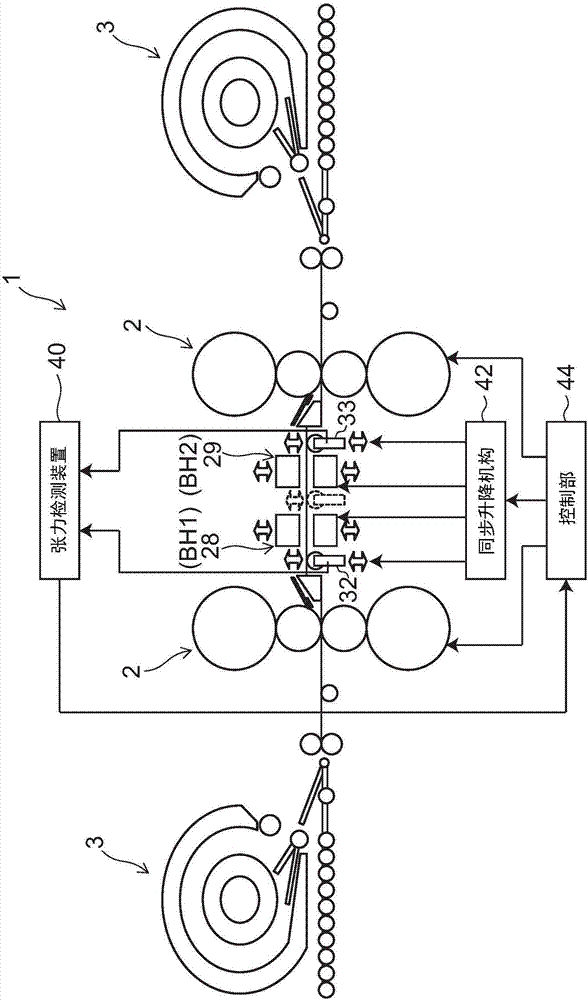
[0049] figure 1 It is a schematic diagram which shows the rolling facility which concerns on 1st Embodiment.
[0050] Such as figure 1 As shown, a reversing steckel mill 1 (rolling facility) includes a pair of coiling furnaces 3 and a plurality of rolling stands 2 arranged between the respective coiling furnaces 3 . Each coiling furnace 3 is a coiling device having a heat preservation function. The reversing steckel mill 1 performs reversing rolling while heating a steel sheet by each coiling furnace 3 . In this example, two rolling stands 2 are installed between the respective coiling furnaces 3 . The number of rolling stands 2 is not limited to two, but may be three or more.
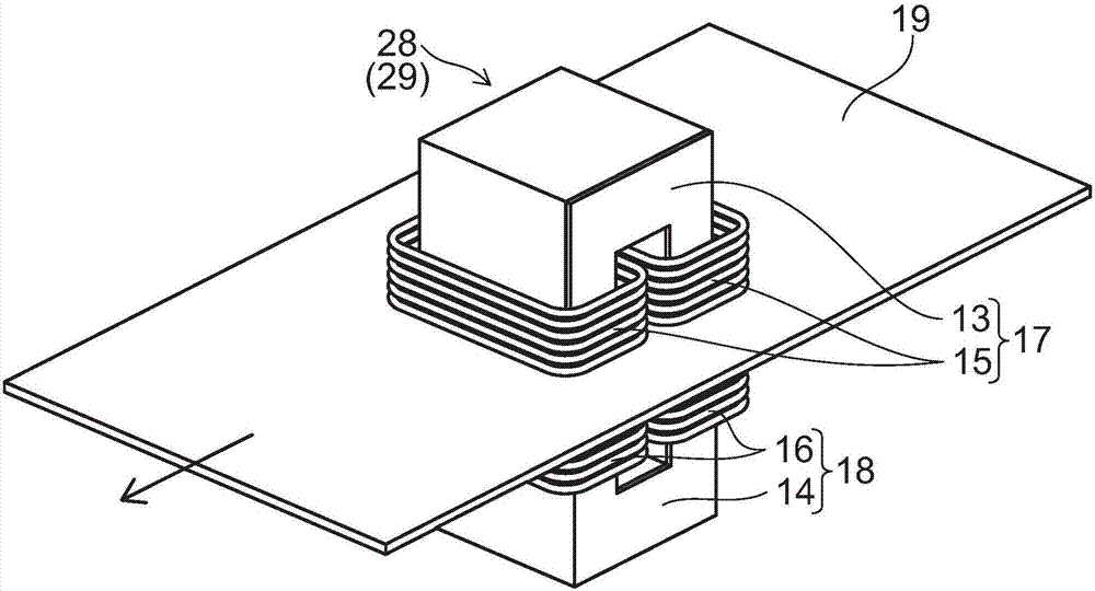
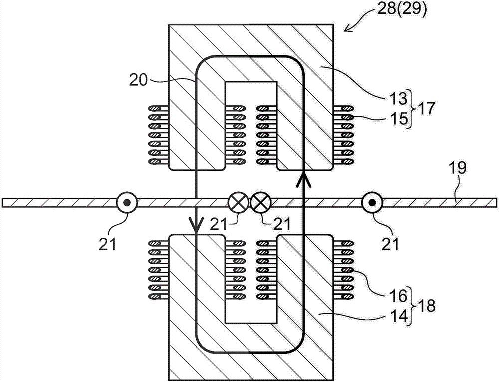
[0051] The reversing steckel mill 1 further includes a pair of strip heaters 28 and 29 (induction heating devices) and a pair of tension rolls 32 and 33 . A horizontal strip heater 28 (BH1) and a strip heater 29 (BH2) capable of changing the gap between the steel plates are arranged between the tw...
no. 2 Embodiment approach
[0073] Figure 7 It is a schematic diagram which shows the rolling facility which concerns on 2nd Embodiment.
[0074] Below, based on Figure 7 A second embodiment of the present invention will be described. In addition, in Figure 7 In , a part of the reversing steckel mill is extracted for illustration.
[0075] exist Figure 7 , between each rolling stand 2, instead of figure 1 The horizontal strip heaters 28, 29 in the middle, and the solenoid type strip heater 35 (BH1) and the solenoid type strip heater 36 (BH2) are set, and the strip heater 35 and the plate The tension roller 32 and the tension roller 33 which can be raised and lowered for inter-stand tension control are also arrange|positioned outside the belt heater 36.
[0076] Figure 8 It is a schematic diagram showing the heating principle of a solenoid-type strip heater.
[0077] Such as Figure 8 As shown, solenoid-type strip heaters 35 , 36 have coiled copper tubes 25 . In the strip heaters 35 and 36,...
no. 3 Embodiment approach
[0081] Figure 9 It is a schematic diagram which shows the rolling facility which concerns on 3rd Embodiment.
[0082] Below, based on Figure 9 A third embodiment of the present invention will be described. In addition, in Figure 9 In , a part of the reversing steckel mill is extracted for illustration.
[0083] Such as Figure 9 shown, in this example, instead of between the rolling stands 2 in figure 1 The tension roll 32 and the tension roll 33 for inter-stand tension control are arranged on the outside of the horizontal strip heater 28 and strip heater 29, and the inter-stand tension is controlled according to the load and torque variation of the two rolling stands 2. Detection and control of the tension between tensionless roll stands. Tension control is performed by the tension detection device 40 and the control unit 44 as described above. Thereby, the speed of the rolling mill is controlled, stable inter-stand tension control is performed, the contact between ...
PUM
 Abstract
Description
Claims
Application Information
 - R&D
- Intellectual Property
- Life Sciences
- Materials
- Tech Scout
- Unparalleled Data Quality
- Higher Quality Content
- 60% Fewer Hallucinations
Browse by: Latest US Patents, China's latest patents, Technical Efficacy Thesaurus, Application Domain, Technology Topic, Popular Technical Reports.
© 2025 PatSnap. All rights reserved.Legal|Privacy policy|Modern Slavery Act Transparency Statement|Sitemap|About US| Contact US: help@patsnap.com


