Cryoablation catheter and system

A technology for ablating catheters and cold sources, applied in catheters, cooling surgical instruments, medical science, etc., can solve the problems of complex structure, damage to surrounding tissues, and high cost, and achieve the effects of reducing damage, preventing heat transfer, and accelerating rewarming.

Active Publication Date: 2017-12-01
CRYOFOCUS MEDTECH (SHANGHAI) CO LTD
View PDF7 Cites 18 Cited by
  • Summary
  • Abstract
  • Description
  • Claims
  • Application Information

AI Technical Summary

Problems solved by technology

However, this heat preservation device adds a lot of parts and has a complex structure, which is only suitable for the treatment of specific target tissues, and the cost is relatively high.
[0006] Although the existing cryoablation catheters fix the inner and outer balloons on the catheter shaft respectively, and fill the inner balloon with refrigerant to achieve the purpose of cooling, but because there is no effective heat-resistant cavity, the formed ice ball often Can cover the area around the treatment site, which can damage surrounding tissues and lead to complications

Method used


Image

  • Cryoablation catheter and system
  • Cryoablation catheter and system
  • Cryoablation catheter and system

Examples


Embodiment 1

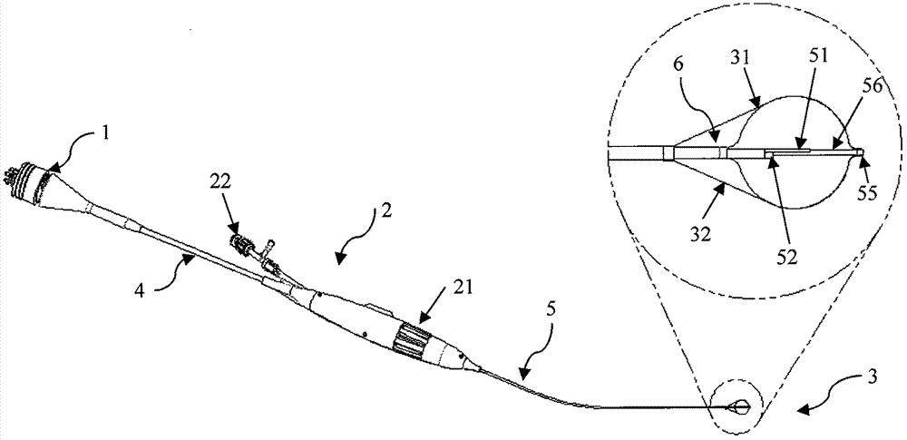
[0070] Such as figure 1 As shown, a cryoablation catheter of the present invention includes: a cold source connector 1, a control handle 2, a freezing unit 3, a flexible connecting tube 4 and a tube body 5, and the tube body 5 having a distal end and a proximal end includes Extended cold source air intake cavity 51 and cold source return air cavity 52; the refrigeration unit 3 is arranged on the distal part of the pipe body 5, including The cavity 52 is in fluid communication with the first balloon body 31 and the second balloon body 32 disposed outside the first balloon body 31 , and the second balloon body 32 expands with the first balloon body 31 . The length of the first capsule 31 is smaller than that of the second capsule 32 . A part of the wall of the first capsule body 31 and the second capsule body 32 is in a bonded state, and the bonded part of the wall of the first capsule body 31 and the second capsule body 32 is frozen energy For the passage to the treatment sit...

Embodiment 2

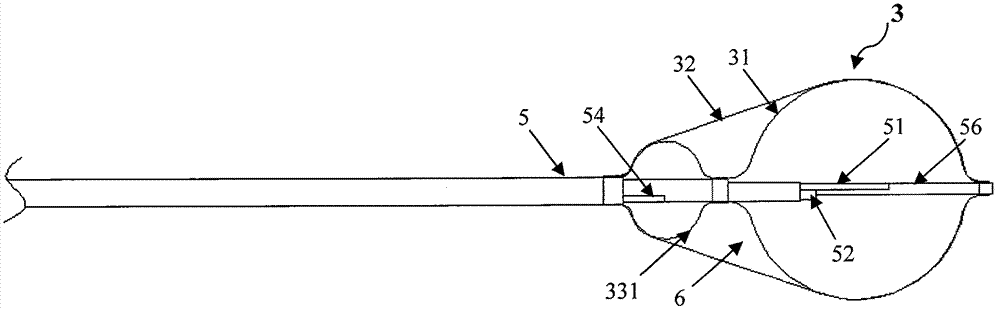
[0078] The difference between this embodiment and Embodiment 1 is that a support structure is provided between the first balloon 31 and the second balloon 32 adjacent to the non-treatment area. When the first balloon 31 And when the second capsule 32 expands, the support structure can support the cavity 6 for isolating energy transmission formed between the first capsule 31 and the second capsule 32, thereby ensuring energy isolation The shape of the transmitted cavity 6 is stable and reliable.

[0079] In one embodiment, the support structure 33 is a balloon 331 disposed at the proximal end of the first balloon body 31 . Such as figure 2 As shown, the tubular body 5 also includes a balloon filling cavity 54 extending axially therethrough, and the balloon filling cavity 54 is in fluid communication with the balloon 331 . During the treatment, a proper amount of refrigerant is first injected into the first capsule 31 to expand the first capsule 31 and the second capsule 32 ....

Embodiment 3

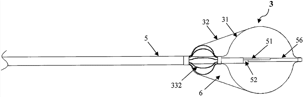
[0081] The difference between this embodiment and Embodiment 2 is that: image 3 As shown, the support structure 33 can be made of one or more memory alloy wires 332 with a preset shape, and the support structure 33, the first balloon body 31 and the second balloon body 32 are in a compressed state before reaching the lesion site . When the first balloon body 31 is delivered to the lesion, the supporting structure 33 can return to a preset shape, thereby providing support. Then the cryoablation treatment is started, and the refrigerant is injected into the first capsule 31 to absorb heat in the treatment area to achieve the effect of cryoablation. The memory alloy wire is preferably nickel-titanium wire. In a preferred embodiment, the preset shape includes a spiral shape (such as Figure 12a shown), cage (such as image 3 shown) or umbrella (such as Figure 16 shown). The memory alloy wire is shaped into a spiral shape, a cage shape or an umbrella shape through heat trea...


PUM


Abstract

The invention relates to a cryoablation catheter and a cryoablation system. The cryoablation catheter comprises a catheter body and a refrigeration unit, the catheter body comprises a cold source air intake cavity which extends in the axial direction and a cold source air return cavity, and the refrigeration unit is arranged at the far end of the catheter body and comprises a first bag body which is communicated with the cold source air intake cavity and the cold source air return cavity through liquid and a second bag body which is arranged outside the first bag body; the length of the first bag body is smaller than that of the second bag body, when the first bag body and the second bag body expand, a cavity which insulates heat transmission is formed between the first bag body and the second bag body, and energy transmission from the cavity to the corresponding space of the refrigeration unit is prevented. The cryoablation catheter can effectively limit a refrigeration energy release area, and accordingly the cryoablation catheter lowers the probability of complications and is wide in application range.

Description

technical field [0001] The invention belongs to the field of cryoablation medical equipment, and in particular relates to a cryoablation catheter and a system. Background technique [0002] Cryoablation is the destruction of cells by forming ice balls inside and outside cells through low temperature. During cryoablation, the cryoprobe is placed on the surface of the tissue, and the low temperature is induced by refrigeration, so that ice balls are formed inside and outside the cells around the probe. As the temperature drops, the cells inside the puck are irreversibly damaged. The cryoablation injury process can be divided into three stages: (1) freezing / rewarming period; (2) hemorrhage and inflammation period; (3) fibrosis period. [0003] Cryoablation is a useful treatment modality in a wide range of catheter-based interventional procedures. For example, cryoablation can be used to ablate the vestibule of the pulmonary vein, resulting in electrical isolation of the pulm...

Claims


Application Information

Patent Timeline
Patent Type & Authority Applications(China)
IPC IPC(8): A61B18/02
CPCA61B18/02A61B2018/00041A61B2018/0025A61B2018/0262A61B2018/00101A61B2018/00255A61B2018/00267A61B2018/0212A61B2018/00577A61B2018/00375A61B2018/00261
Inventor 刁月鹏杨东辉李攀
Owner CRYOFOCUS MEDTECH (SHANGHAI) CO LTD
Why Eureka
Try Eureka