Lifting device gravitational potential energy pressure-volume storage system
A technology of gravitational potential energy and lifting devices, which is applied to fluid pressure actuation system components, lifting devices, fluid pressure actuation devices, etc., can solve problems such as waste, and achieve the effect of less energy conversion links and high conversion efficiency
- Summary
- Abstract
- Description
- Claims
- Application Information
AI Technical Summary
Problems solved by technology
Method used
Image
Examples
Embodiment 1
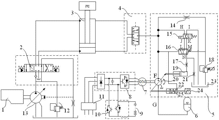
[0026] Attached below figure 1 The specific embodiment 1 of the present invention will be further described.
[0027] as attached figure 1 As shown, an embodiment 1 of a lifting device gravity potential energy pressure volume storage system is implemented. In the specific implementation, the engine 1 adopts a diesel engine, the main control valve 2 is a three-position six-power ratio multi-way reversing valve, and the lifting hydraulic cylinder 3 adopts a single rod structure, the conversion control valve 4 is an electric control structure, and the pressure is continuously adjustable. The hydraulic motor / pump 5 adopts the principle of an axial plunger structure. The hydraulic accumulator 6 is a piston type, and the motor / generator 7 is a permanent magnet. Synchronous structure, the motor speed controller 8 adopts vector control mode, the supercapacitor 9 is composed of basic modules connected in series and parallel, the DC-DC converter 10 can bidirectionally step up and step ...
Embodiment 2
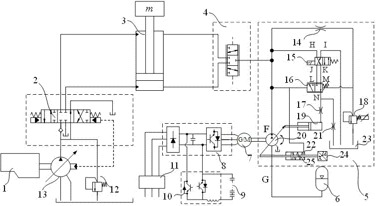
[0034] Attached below figure 2 The specific embodiment 2 of the present invention will be further described.
[0035] as attached figure 2 As shown, the connection structure and working mode of the components of the energy recovery control circuit and the conversion control valve 4 in this specific embodiment are the same as those in Embodiment 1, the difference being that the main drive circuit is a positive flow control circuit. The main hydraulic pump 13 is a variable-displacement pump controlled by electronic proportion, and its displacement is proportional to the set signal, that is, as the set signal increases, the displacement of the main hydraulic pump 13 also increases.
Embodiment 3
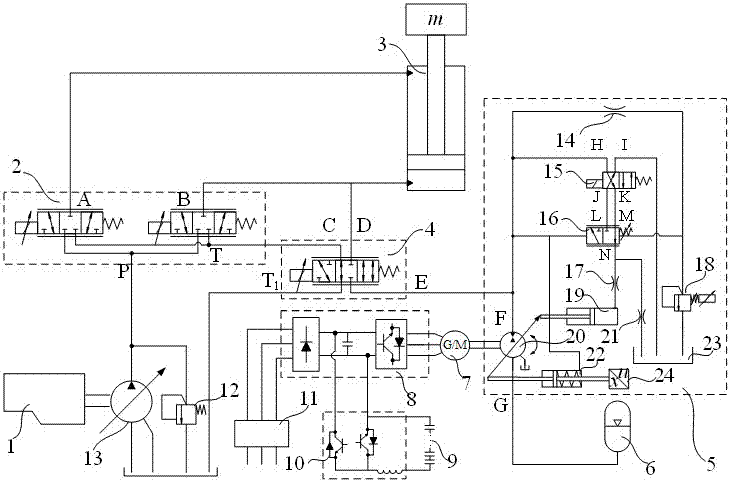
[0037] Attached below image 3 A further description will be made to the specific embodiment 3 of the present invention.
[0038] as attached image 3 As shown, this embodiment is to further improve the structure of embodiment 2 on the basis of specific embodiment 2. The structural improvement is that the main control valve 2 adopts an independent control structure for oil inlet and outlet, and consists of two three-position The three-way proportional directional valve is composed of a three-position four-way solenoid valve; the working oil port of the first proportional directional valve is connected with the rod chamber of the lifting hydraulic cylinder 3, and the working oil port of the second proportional directional valve It communicates with the rodless chamber of the lifting hydraulic cylinder 3, the oil outlet of the main hydraulic pump 13 communicates with the oil inlet of the first and second proportional directional valves, and the oil return ports of the first and...
PUM
| Property | Measurement | Unit |
|---|---|---|
| Diameter | aaaaa | aaaaa |
Abstract
Description
Claims
Application Information
 - R&D
- Intellectual Property
- Life Sciences
- Materials
- Tech Scout
- Unparalleled Data Quality
- Higher Quality Content
- 60% Fewer Hallucinations
Browse by: Latest US Patents, China's latest patents, Technical Efficacy Thesaurus, Application Domain, Technology Topic, Popular Technical Reports.
© 2025 PatSnap. All rights reserved.Legal|Privacy policy|Modern Slavery Act Transparency Statement|Sitemap|About US| Contact US: help@patsnap.com


