Device and method for laser processing wafer

A laser processing and wafer technology, applied in metal processing, laser welding equipment, metal processing equipment, etc., can solve the problems of low-K material sticking and falling off, hot burning phenomenon in the center of the spot, reducing chip yield, etc., to improve the score. Beam processing capability, small heat-affected zone, and high uniformity

Active Publication Date: 2018-10-09
北京中科镭特电子有限公司
View PDF6 Cites 0 Cited by
  • Summary
  • Abstract
  • Description
  • Claims
  • Application Information

AI Technical Summary

Problems solved by technology

[0003] At present, when cutting wafers below the 90nm node, the substrate is generally covered with Low-K materials, because the adhesion between the Low-K materials and the substrate is not as good as that of materials with a dielectric constant (such as dioxide Silicon, etc.) and the base substrate, therefore, when the wafer covered with Low-K material is cut to form a groove, it will cause the adhesion and detachment of the Low-K material, thereby reducing the chip yield, Even causing fragmentation of the wafer substrate, wherein the "groove" refers to the substrate that does not penetrate the wafer and forms grooves on its upper surface
[0004] At the same time, when the laser is used to cut the wafer, since the intensity distribution of the laser light source conforms to the Gaussian distribution, that is, the light intensity is the strongest at the center of the spot, and the energy at the edge of the spot decreases gradually according to the characteristics of the Gaussian distribution. When the optically processed Gaussian spot is cut with a single beam, the center of the spot is prone to strong thermal burning phenomenon, and then the heat-affected area is large and damages the wafer

Method used


Image

  • Device and method for laser processing wafer
  • Device and method for laser processing wafer
  • Device and method for laser processing wafer

Examples


Embodiment Construction

[0065] In order to make the purpose, technical solutions and advantages of the embodiments of the present invention clearer, the technical solutions in the embodiments of the present invention will be clearly and completely described below in conjunction with the drawings in the embodiments of the present invention. Obviously, the described embodiments It is only some embodiments of the present invention, but not all embodiments. Based on the embodiments of the present invention, all other embodiments obtained by persons of ordinary skill in the art without making creative efforts belong to the protection scope of the present invention.

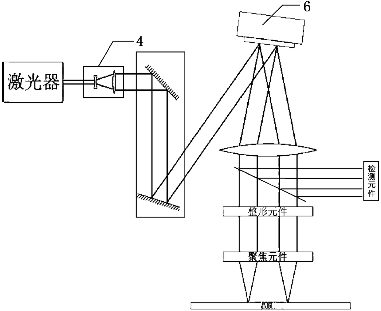
[0066] Embodiments of the present invention provide a device for laser processing wafers, such as figure 1 As shown, the device includes:

[0067] a laser for emitting a laser beam;

[0068] A beam expander and collimator element is used to expand and collimate the laser beam to form a parallel beam;

[0069] Phase-controlled liquid crysta...


PUM


Abstract

The invention provides a device and method for wafer laser processing. The device comprises a laser unit, a beam expanding and collimating element, a phase-controlled-type silicon-based liquid crystal and a focusing element; the laser unit is used for emitting laser beams; the beam expanding and collimating element is used for beam expanding and collimating of the laser beams to form the parallel light beams; the phase-controlled-type silicon-based liquid crystal is used for conducing energy distribution modulation on the parallel light beams to form random customized multi-light-beam assemblies or conducting shape-correction treatment to form flattop light spots to be emitted to the focusing element; and the focusing element is used for emitting the random customized multi-light-beam assemblies or the flattop light spots to the upper surface of a wafer and removing Low-K materials of the upper surface of the wafer in the pre-set cutting way direction. According to the device and method for wafer laser processing, through the phase-controlled-type silicon-based liquid crystal, energy distribution modulation or shape-correction treatment is conducted on the parallel light beams to improve the work efficiency and accuracy of the processing method and the uniformity of wafer separation, and the device and method for wafer laser processing can be suitable for the requirements of the various flattop light spots.

Description

technical field [0001] The invention relates to the technical field of semiconductors, in particular to a device and method for laser processing wafers. Background technique [0002] With the gradual development of intelligence, the requirements for chip manufacturing and packaging and testing are increasing, especially for semiconductor, organic, inorganic and other materials, which are processed and manufactured in the range of micron and nanoscale. [0003] At present, when cutting wafers below the 90nm node, the substrate is generally covered with Low-K materials, because the adhesion between the Low-K materials and the substrate is not as good as that of materials with a dielectric constant (such as dioxide Silicon, etc.) and the base substrate, therefore, when the wafer covered with Low-K material is cut to form a groove, it will cause the adhesion and detachment of the Low-K material, thereby reducing the chip yield, It even causes fragmentation of the wafer substrat...

Claims


Application Information

Patent Timeline
Patent Type & Authority Patents(China)
IPC IPC(8): B23K26/364B23K26/06B23K26/073B23K26/04B23K26/067B23K26/064
CPCB23K26/04B23K26/06B23K26/0648B23K26/067B23K26/073B23K26/364B23K2101/40
Inventor 张紫辰侯煜刘嵩
Owner 北京中科镭特电子有限公司
Why Eureka
Try Eureka