Production method of water channel groove prefabricated members

A production method and prefabricated parts technology, applied in the manufacture of tools, ceramic molding machines, molds, etc., can solve the problems of not being able to maximize the use of water sources, waste of labor and working time, and affect the service life of beams and grooves, so as to improve alkali resistance Aggregate reaction performance, improvement of work efficiency and shortening of construction period

Pending Publication Date: 2017-12-08
潘春光
View PDF15 Cites 2 Cited by
  • Summary
  • Abstract
  • Description
  • Claims
  • Application Information

AI Technical Summary

Problems solved by technology

[0009] The deficiencies in the prior art include: 1. The construction period is long, the cost is high, and a lot of labor is required. During the construction period, it is easily affected by the weather, and a large construction site needs to be excavated. It is easily damaged, difficult to maintain, and cannot Reuse, demolition is quite troublesome, easy to damage the original land environment, etc.; 2. The water channel channel is easily squeezed, deformed or damaged by the pressure of the soil layer, which not only greatly affects the service life of the beam channel, but also greatly increases the cost input and wastes Resources; 3. When installing and docking water channels and channels, the joints are poorly sealed and prone to water leakage, resulting in the failure to maximize the use of water sources; 4. There are many steps in the production of prefabricated parts for water channels and channels, and the process of taking molds is too cumbersome and a great waste Reduced labor and working hours, low work efficiency

Method used


Image

  • Production method of water channel groove prefabricated members
  • Production method of water channel groove prefabricated members
  • Production method of water channel groove prefabricated members

Examples


Embodiment 1

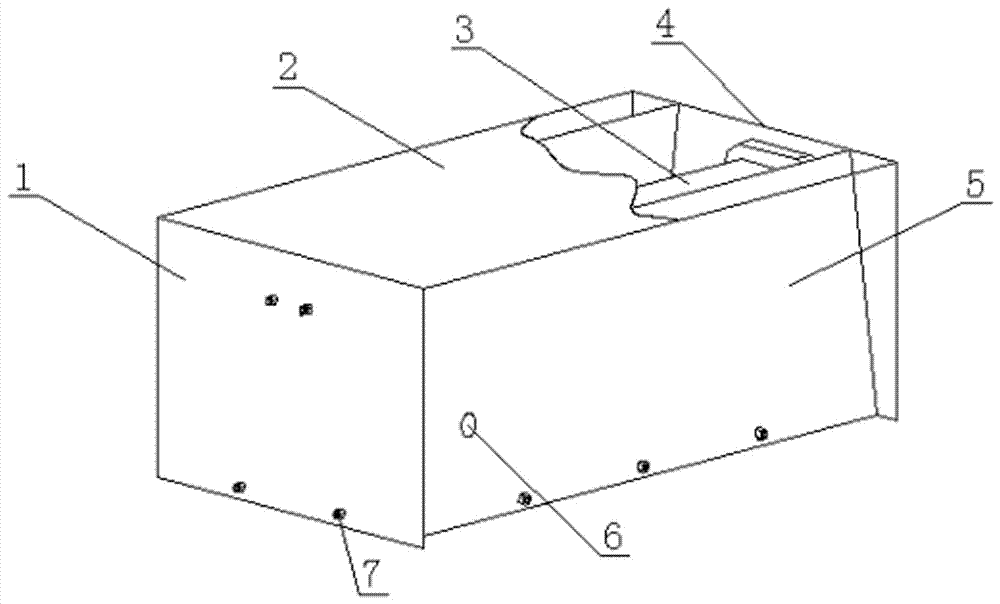
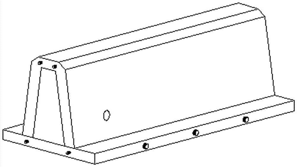
[0050] see Figures 1 to 7 Shown, a kind of production method of drain channel prefabricated part, described method comprises the following steps:

[0051] (1) Make the mold required for the same shape as the prefabricated part of the canal, place the mold upside down, with the bottom of the mold facing up, and pour concrete from the bottom;

[0052] (2) Evenly spray release oil or pad plastic film on the inside of the mold;

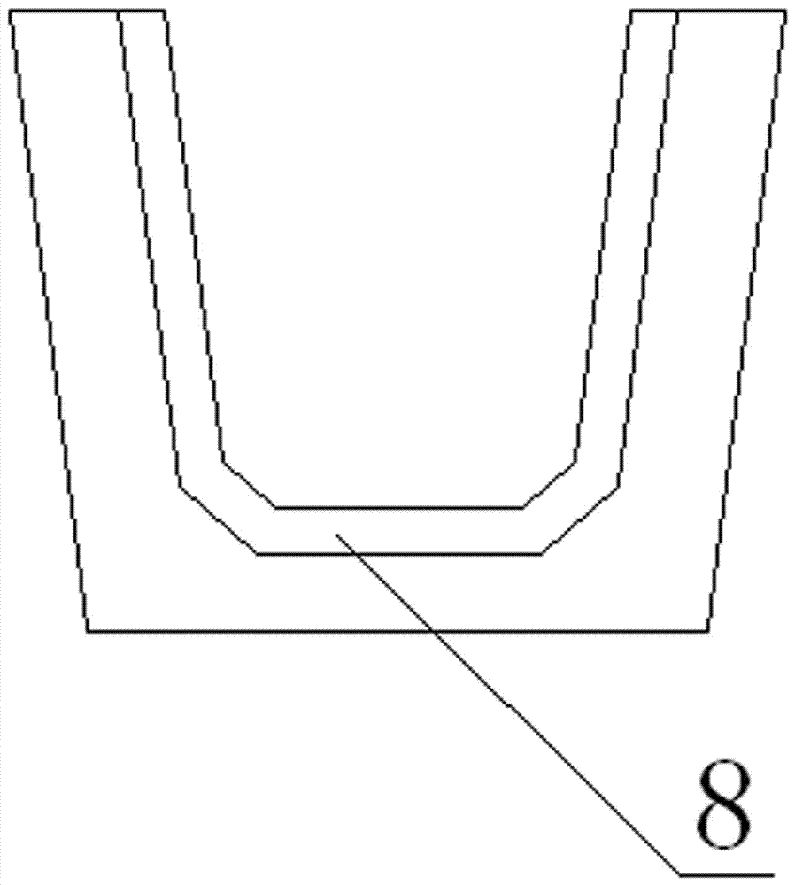
[0053] (3) Put the prepared steel bar skeleton into the pouring mold, and adjust the concrete protective layer. The groove edge of the steel bar structure is equipped with stress bars according to the internal and external stress conditions, and the bottom of the groove is pressed according to the upper and lower loads. The force situation configures the stress bars, decomposes the configured steel bars into shapes that can be processed, and then welds them into unit components, welds several unit components with longitudinal steel bars to form a reinfo...

Embodiment 2

[0065] see Figures 1 to 7 Shown, a kind of production method of drain channel prefabricated part, described method comprises the following steps:

[0066] (1) Make the mold required for the same shape as the prefabricated part of the canal, place the mold upside down, with the bottom of the mold facing up, and pour concrete from the bottom;

[0067] (2) Evenly spray release oil or pad plastic film on the inside of the mold;

[0068] (3) Put the prepared steel bar skeleton into the pouring mold, and adjust the concrete protective layer. The groove edge of the steel bar structure is equipped with stress bars according to the internal and external stress conditions, and the bottom of the groove is pressed according to the upper and lower loads. The force situation configures the stress bars, decomposes the configured steel bars into shapes that can be processed, and then welds them into unit components, welds several unit components with longitudinal steel bars to form a reinfo...

Embodiment 3

[0080] see Figures 1 to 7 Shown, a kind of production method of drain channel prefabricated part, described method comprises the following steps:

[0081] (1) Make the mold required for the same shape as the prefabricated part of the canal, place the mold upside down, with the bottom of the mold facing up, and pour concrete from the bottom;

[0082] (2) Evenly spray release oil or pad plastic film on the inside of the mold;

[0083] (3) Put the prepared steel bar skeleton into the pouring mold, and adjust the concrete protective layer. The groove edge of the steel bar structure is equipped with stress bars according to the internal and external stress conditions, and the bottom of the groove is pressed according to the upper and lower loads. The force situation configures the stress bars, decomposes the configured steel bars into shapes that can be processed, and then welds them into unit components, welds several unit components with longitudinal steel bars to form a reinfo...


PUM

PropertyMeasurementUnit
particle sizeaaaaaaaaaa

Abstract

The invention discloses a production method of water channel groove prefabricated members. The production method comprises the following steps that (1) a pouring die needed by the water channel prefabricated members in same shapes is manufactured, the die is inversely placed, and the bottom of the die is upward; (2) the inner side of the die is evenly coated with mold oil, or a plastic thin film is paved on the inner side of the die; (3) a manufactured reinforcement cage is arranged in the pouring die in a sleeved manner, and a concrete protection layer is adjusted well; (4) concrete needed by pouring is manufactured on site, wherein the concrete is poured in from the middle of the bottom of the die and is evenly spread to the two ends, a tamping device is used for vibrating for 1 minute to 3 minutes, then the upper surface of a groove opening of the die is troweled, and a die cover plate is closed; and (5) the water channel prefabricated members obtained after concrete pouring are maintained on site, during maintenance, edge dies can be detached after the time.temperature is larger than 500 h.DEG C, during watering maintenance, an inner die can be detached after the time.temperature is larger than 1500 h.DEG C, the prefabticated members are stacked in a concentrated manner after the inner die is detached, and during maintenance, factory leaving for use can be achieved after the time.temperature is larger than 2000 h.DEG C. The production method has the beneficial effect that the construction efficiency can be greatly improved.

Description

technical field [0001] The invention relates to the field of water conservancy engineering, in particular to a production method of a prefabricated part of a water channel and trench. Background technique [0002] Canals are the main tools for irrigation and drainage projects such as farmland water conservancy, transportation, municipal administration, sewage, and drainage in rainy days, and precast concrete U-shaped channel molds are one of the main tools for producing channel channels. [0003] With the vigorous development of modern agriculture and water conservancy infrastructure in our country, the scale of national and local investment in agriculture and water conservancy infrastructure is increasing. my country is a country with relatively backward agricultural technology, with a vast territory and uneven distribution of water resources, especially in the western region, where water resources are very scarce in some provinces and cities. At the same time, due to unre...

Claims


Application Information

Patent Timeline
Patent Type & Authority Applications(China)
IPC IPC(8): B28B7/22B28B7/38B28B1/093B28B11/24B28B23/02
CPCB28B1/0935B28B7/22B28B7/38B28B11/245B28B23/02
Inventor 潘春光
Owner 潘春光
Why Eureka
Try Eureka