Optical fiber cutting device and cutting method

A cutting device and cutting method technology, which are applied in the field of optical fiber cutting for cutting optical fibers and cutting devices for cutting optical fibers, can solve the problems of uncontrollable slopes, easy movement of optical fibers, etc., and achieve high cutting efficiency, wide application range and smooth section. Effect

Pending Publication Date: 2017-12-08
NANJING UNIV OF POSTS & TELECOMM INST AT NANJING CO LTD
View PDF8 Cites 7 Cited by
  • Summary
  • Abstract
  • Description
  • Claims
  • Application Information

AI Technical Summary

Problems solved by technology

[0003] The technical problem mainly solved by the present invention is to provide an optical fiber cutting device to solve the problem in the prior art that the optical fiber is easy to move and cut an uncontrollable slope when the optical fiber is cut. At the same time, the present invention also provides an optical fiber cutting method , the optical fiber cut by this method will not appear the uncontrollable slope when the optical fiber is cut in the prior art

Method used


Image

  • Optical fiber cutting device and cutting method
  • Optical fiber cutting device and cutting method

Examples


Embodiment Construction

[0032]In describing specific embodiments of the present invention, it should be understood that the terms "center", "longitudinal", "transverse", "upper", "lower", "front", "rear", "left", " The orientation or positional relationship indicated by "right", "vertical", "horizontal", "top", "bottom", "inner", "outer", etc. is based on the orientation or positional relationship shown in the drawings, and is for convenience only The present invention is described and simplified descriptions do not indicate or imply that the device or element referred to must have a specific orientation, be constructed and operate in a specific orientation, and thus should not be construed as limiting the present invention. In addition, the terms "first", "second", etc. are used for descriptive purposes only, and should not be understood as indicating or implying relative importance or implicitly specifying the quantity of the indicated technical features. Thus, a feature defined as "first", "second...


PUM


Abstract

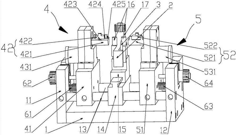
The invention discloses an optical fiber cutting device. The device comprises a base; the base is provided with a cutter holder; the cutter holder is provided with a cutter; the base is provided with a left clamping mechanism and a right clamping mechanism which are located at two sides of the cutter holder respectively; the left clamping mechanism comprises a left clamping seat, a left clamping assembly arranged on the left clamping seat and a left driving assembly for driving the left clamping assembly to rotate; and the right clamping mechanism comprises a right clamping seat, a right clamping assembly arranged on the right clamping seat and a right driving assembly for driving the right clamping assembly to rotate. According to the optical fiber cutting device of the invention, the left clamping assembly and the right clamping assembly are adopted to firmly clamp an optical fiber; the optical fiber rotates on the cutter; the cutter is adopted to cut the outer surface of the optical fiber so as to leave scratches on the outer surface of the optical fiber, so that the optical fiber will be fractured at the scratches; the fractured surfaces of the optical fiber are flat; and cutting efficiency is high; and the optical fiber does not move during the cutting process. The invention also discloses an optical fiber cutting method. According to the method, the optical fiber is rotated; the cutter cuts the outer surface of the optical fiber so as to leave scratches on the outer surface of the optical fiber, so that the optical fiber is fractured, and the optical fiber can form a certain cutting surface angle.

Description

technical field [0001] The invention belongs to the field of cutting tools, and in particular relates to a cutting device for cutting optical fibers, and also relates to an optical fiber cutting method for cutting optical fibers. Background technique [0002] Optical fiber can be divided into quartz optical fiber, soft glass optical fiber, plastic optical fiber, composite optical fiber, etc. according to the raw material. The existing optical fiber cutter, such as Chinese patent number: CN201620027817.2, the patent name is: bilaterally cut quartz optical fiber cutter, The disclosed double-sided cutting optical fiber cutter includes a main body, the main body includes a base, an optical fiber holder, a knife and a pair of lower holders, the base has an opening, the knife includes a knife holder and a blade, and the knife holder is located on the In the space below the base, the blade is assembled on the tool holder, the upper end of the blade protrudes upwards from the openin...

Claims


Application Information

Patent Timeline
IPC IPC(8): G02B6/25
CPCG02B6/25
Inventor 邹辉史上清肖鹏熊慧马雷
Owner NANJING UNIV OF POSTS & TELECOMM INST AT NANJING CO LTD
Why Eureka
Try Eureka