
High time resolution optical imaging system based on optical fiber image transmitting bundle

A technology of optical imaging system and optical fiber image transmission beam, which is applied in the coupling of optics, optical components, and optical waveguides, etc., to achieve the effects of high two-dimensional spatial resolution, high time resolution, and large detection area

Active Publication Date: 2017-12-08
LASER FUSION RES CENT CHINA ACAD OF ENG PHYSICS
View PDF6 Cites 3 Cited by
  • Summary
  • Abstract
  • Description
  • Claims
  • Application Information

AI Technical Summary

Problems solved by technology

The photocathode converts the light pulse incident from the slit into a photoelectron pulse, and then accelerates and drifts through a high electric field to focus on the small hole of the anode, and then deflects it through a deflection plate whose electric field direction is perpendicular to the slit, because the deflection electric field increases linearly with time , so the light pulses at different times will be deflected to different positions in space after the above process, that is, the time change of the signal is converted into a one-dimensional change of space for recording, while the other dimension of space retains the space to be measured The spatial resolution ability, therefore, the optical streak camera can only resolve one-dimensional direction in space

Method used


Image

  • High time resolution optical imaging system based on optical fiber image transmitting bundle
  • High time resolution optical imaging system based on optical fiber image transmitting bundle
  • High time resolution optical imaging system based on optical fiber image transmitting bundle

Examples


Embodiment Construction

[0019] The present invention will be further described below in conjunction with embodiment and accompanying drawing.

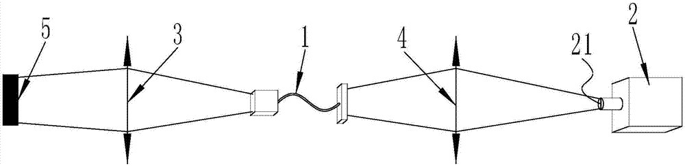
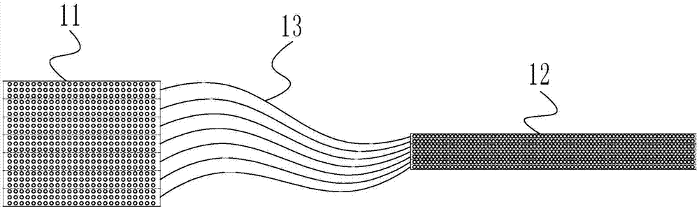
[0020] like figure 1 As shown, a high time-resolution optical imaging system based on optical fiber image transmission bundle, including optical fiber image transmission bundle assembly 1, optical streak camera 2, incident imaging lens 3 and exit imaging lens 4, wherein the optical fiber image transmission bundle The assembly 1 is located between the incident imaging lens 3 and the outgoing imaging lens 4 , and the outgoing imaging lens 4 is located between the optical fiber image transmission bundle assembly 1 and the optical streak camera 2 . The optical pulse signal fed back from the target to be measured 5 is imaged on the optical fiber image transmission bundle assembly 1 through the incident imaging lens 3, and then the optical pulse signal is transmitted through the optical fiber image transmission bundle assembly 1, and finally exits the imaging lens ...


PUM


Abstract

The invention discloses a high time resolution optical imaging system based on an optical fiber image transmitting bundle. The system comprises an optical fiber image transmitting bundle assembly, an optical streak camera, an incident imaging lens and an emergent imaging lens. The optical fiber image transmitting bundle assembly is located between the incident imaging lens and the emergent imaging lens. The emergent imaging lens is located between the optical fiber image transmitting bundle assembly and the optical streak camera. The optical fiber image transmitting beam assembly comprises an incident end head, an emergent end head and m groups of optical fiber bundles. Lengths of the groups of optical fiber bundles are different. Incident ends of fiber cores of each group of optical fiber bundles are uniformly distributed on an end surface of the incident end head in a one-dimensional or two-dimensional mode. Emergent ends of the fiber cores of each group of optical fiber bundles are uniformly distributed on an end surface of the emergent end head in a one-dimensional mode. By using the high time resolution optical imaging system based on the optical fiber image transmitting bundle, the structure is novel and is easy to realize; a high time resolution and a high two-dimensional space distinguishing capability are possessed; and simultaneously the whole system possesses a large detection area and a suitable range is wide.

Description

technical field [0001] The invention relates to a recording device for high energy density physics research, in particular to a high time resolution optical imaging system based on an optical fiber image transmission beam. Background technique [0002] In the research of high energy density physics, many physical processes occur on a very short time scale. In order to diagnose and detect such physical processes, it is necessary to use equipment with high time resolution to record them. The optical streak camera is such a recording device with high time resolution capability. Its time resolution is as high as about 5 ps (picosecond), and it has a very wide range of applications in high energy density physics, especially in the research of laser inertial confinement fusion. For example, the variation process of interference fringes with time is recorded in VISAR, and the variation process of scattered light spectrum with time is recorded by coupling spectrometer in backscatter...

Claims


Application Information

Patent Timeline
IPC IPC(8): G02B6/42
CPCG02B6/4204G02B6/4249
Inventor 理玉龙刘祥明査为懿魏惠月杨冬吴宇际王峰徐涛彭晓世刘永刚梅雨
Owner LASER FUSION RES CENT CHINA ACAD OF ENG PHYSICS
Learn More