Single-stage-type photovoltaic off-grid inverter with high frequency rectification control and control method thereof

A high-frequency rectification and high-frequency transformer technology, applied in the field of electricity, can solve the problems of micro-inverter battery boards not isolated, difficult to increase the power, and increase the volume of the inverter, so as to improve the overall efficiency and reliability, reduce the Small size, reduce the effect of control difficulty

Active Publication Date: 2017-12-08
QINGDAO UNIV
View PDF2 Cites 2 Cited by
  • Summary
  • Abstract
  • Description
  • Claims
  • Application Information

AI Technical Summary

Problems solved by technology

[0002] Traditional photovoltaic off-grid micro-inverters generally have the following three structural forms: the first is a non-isolated two-stage structure, that is, the front stage uses a non-isolated Boost circuit to boost the voltage, and the latter stage uses an H-bridge inverter. Its advantages The circuit is relatively simple, but the disadvantage is that the output of the micro-inverter is not isolated from the battery board, which will bring safety hazards and its efficiency is low
The second is an isolated two-stage structure, that is, the front stage uses an isolated voltage or current-type half-bridge LLC circuit to boost the voltage, and the latter stage uses an H-bridge inverter. The advantage is that the output of the micro-inverter and the battery board realize electrical Isolation eliminates potential safety hazards, and its pre-stage circuit can realize soft switching through resonance. The efficiency of the pre-stage circuit is relatively high. The disadvantage is that the inverter is relatively large in size and high in cost. The pre-stage is a current-type half-bridge LLC. The circuit control is relatively complicated, and two inductors are required, which increases the size of the inverter; the front stage is a voltage-type half-bridge LLC circuit control is relatively complicated, and the upper and lower switch tubes of the bridge arm are easy to pass through and burn the circuit; the third is isolation Type single-stage structure, currently the primary side of the transformer generally adopts flyback type, interleaved flyback type or interleaved flyback active clamping circuit, and the secondary side of the transformer adopts power frequency inverter, that is, the electrical isolation can be realized by using the primary circuit It is also reversible, eliminating the post-stage H-bridge inverter circuit. For flyback or interleaved flyback circuits, the advantage is that the circuit structure is simple and easy to control. The disadvantage is that the transformer is unidirectionally excited, the magnetic core is easily saturated, and the power It is difficult to make it bigger, the switching tube cannot realize soft switching, and the efficiency is relatively low; for the interleaved flyback active clamp circuit, the switching tube in the active clamping branch and the main switching tube are complementary conduction, and the two The switching tubes have realized zero-voltage soft switching, and the withstand voltage of the switching tubes has been reduced, and the efficiency has been relatively improved. However, the existing transformer is unidirectionally excited, the magnetic core is easily saturated, and the power is difficult to increase, which increases the complexity of control.
[0003] Combining the three structural forms of traditional photovoltaic off-grid small inverters, for isolated or non-isolated two-stage small inverters, the latter stage generally uses H-bridge inverters. The shortcomings of burning out the circuit, high difficulty in control, low reliability, and low efficiency, coupled with the cascading of the front and rear stages, the volume of the inverter increases, the reliability decreases, and the efficiency is further reduced. At present, it is gradually being isolated. However, the isolated single-stage structure also has the problems of one-way excitation of the transformer and complex control

Method used


Image

  • Single-stage-type photovoltaic off-grid inverter with high frequency rectification control and control method thereof
  • Single-stage-type photovoltaic off-grid inverter with high frequency rectification control and control method thereof
  • Single-stage-type photovoltaic off-grid inverter with high frequency rectification control and control method thereof

Examples


Embodiment

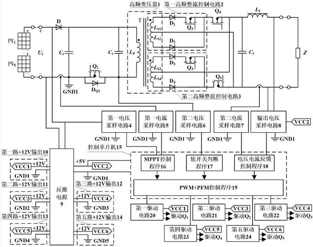
[0020] The main structure of the single-stage photovoltaic off-grid inverter with high-frequency rectification control in this embodiment includes a reverse cut-off diode D, a capacitor C i , Resonant capacitance C r , the first switching tube Q 1 , Freewheeling diode D Q1 , high-frequency transformer 1, first high-frequency rectification control circuit 2, second high-frequency rectification control circuit 3, fourth switching tube Q 4 , the fifth switching tube Q 5 , filter capacitor C f , filter inductance L f , a first voltage sampling circuit 4, a first current sampling circuit 5, a second voltage sampling circuit 6, a second current sampling circuit 7, an output voltage sampling circuit 8, a flyback power supply 9, a control microcontroller 15, a first drive circuit 20, The second drive circuit 21, the third drive circuit 22, the fourth drive circuit 23 and the fifth drive circuit 24; the input voltage U i through the reverse blocking diode D and by the capacitor C...


PUM


Abstract

The invention belongs to the electrical technology field and relates o a single-stage-type off-grid inverter with high frequency rectification control and a control method thereof. On a primary side of a transformer, one switch tube is used to realize solar photovoltaic inversion, and the switch tube simultaneously is used to realize zero voltage opening and closing and make an isolation transformer realize bidirectional excitation. Two sets of high frequency rectification control circuits of a secondary side of the transformer make that an unsymmetrical voltage output by a secondary side winding of the transformer is effectively used. Through controlling a conduction duty ratio of a high frequency switch tube, MPPT is realized. A controllable inversion switch tube of the secondary side of the transformer carries out power-frequency alternative conduction. A resonant capacitor which is parallel to the primary side of the transformer and a transformer primary side inductor carry out resonance so that a high voltage gain exists between output and input of the inverter, and through changing a switch frequency of a primary side switch tube, adjustment can be performed. The structure of the circuit is simple, the size is small, cost is low, efficiency is high, the inverter is easy to control, reliability is high and the inverter can be widely applied.

Description

Technical field: [0001] The invention belongs to the field of electrical technology, and relates to an off-grid inverter and a control method thereof, in particular to a single-stage off-grid inverter with high-frequency rectification control whose input is a solar panel assembly and a control method thereof . Background technique: [0002] Traditional photovoltaic off-grid micro-inverters generally have the following three structural forms: the first is a non-isolated two-stage structure, that is, the front stage uses a non-isolated Boost circuit to boost the voltage, and the latter stage uses an H-bridge inverter. Its advantages The circuit is relatively simple, but the disadvantage is that the output of the micro-inverter is not isolated from the battery board, which will bring safety hazards, and its efficiency is low. The second is an isolated two-stage structure, that is, the front stage uses an isolated voltage or current-type half-bridge LLC circuit to boost the vol...

Claims


Application Information

Patent Timeline
Patent Type & Authority Applications(China)
IPC IPC(8): H02M7/48
CPCH02M7/4807H02M7/4818Y02B70/10Y02E10/56
Inventor 王春芳赵永强王锐
Owner QINGDAO UNIV
Why Eureka
Try Eureka