Method for processing glass camera lens and device therefor

A processing method and camera technology, applied in glass cutting devices, glass production, glass manufacturing equipment, etc., can solve the problems of unsatisfactory product performance, low processing profit, high processing time cost and labor cost, and achieve low cost , easy to obtain, easy to control effects

Active Publication Date: 2019-11-05
LENS TECH
View PDF8 Cites 0 Cited by
  • Summary
  • Abstract
  • Description
  • Claims
  • Application Information

AI Technical Summary

Problems solved by technology

And the processing of current glass lens all adopts the method of monolithic processing, has the following defects: 1, monolithic forming, the time cost of processing and labor cost are high, and processing profit is lower and lower, and the sales price of current glass camera product 2. The performance of the product cannot meet the requirements, and the performance of the glass camera obtained through the existing technology is: the extrusion cannot exceed 4.0kg / cm 2 , the falling ball 10g cannot exceed 10cm, which cannot meet the actual needs

Method used


Image

  • Method for processing glass camera lens and device therefor
  • Method for processing glass camera lens and device therefor
  • Method for processing glass camera lens and device therefor

Examples


Embodiment 1

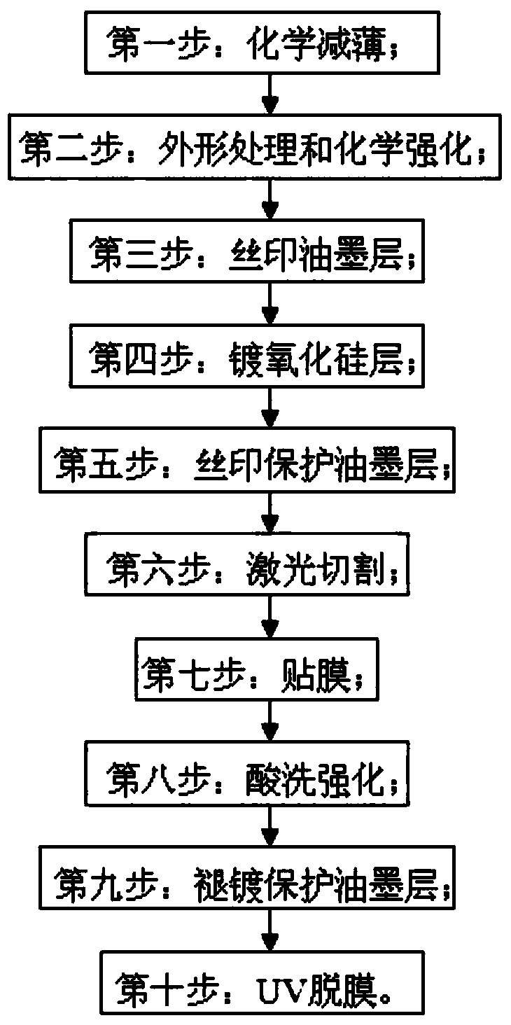
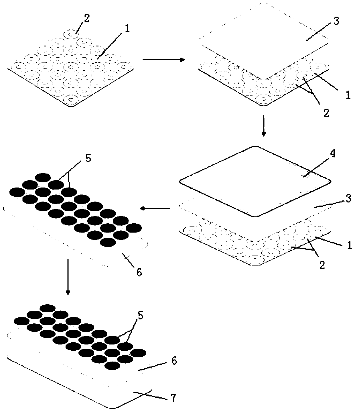
[0057] see figure 1 as well as figure 2 , a method for processing a glass camera lens, the details are as follows:

[0058] Prepare the equipment first, specifically: prepare a treatment tank for chemical thinning and pickling strengthening, the treatment tank is a U-shaped tank resistant to the compound acid; prepare a CNC machine tool for processing the workpiece into the required shape; prepare a glass chemical strengthening furnace for chemical strengthening of the workpiece after shape treatment; prepare a fully automatic CCD positioning screen printing machine for silk screen printing ink layer and silk screen layer protection on the surface of the workpiece Ink layer; prepare a vacuum sputtering coating machine for electroplating a layer of silicon oxide on the ink layer of the workpiece; prepare a picosecond laser cutting machine for cutting the workpiece into multiple glass cameras by laser cutting machine Lens samples; prepare a film laminating machine for affixin...

Embodiment 2- Embodiment 6

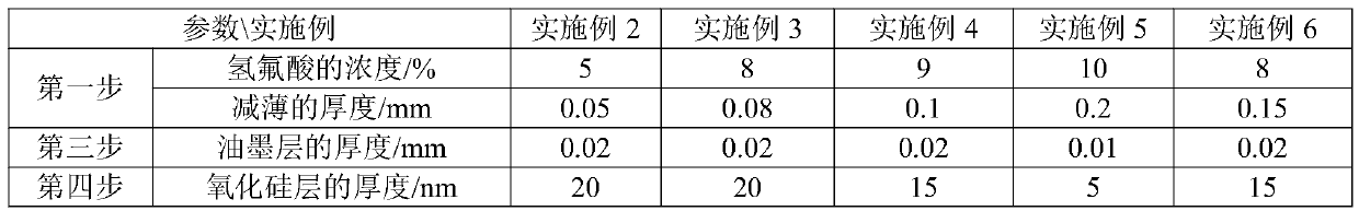
[0073] Embodiment 2-Embodiment 6 differs from Embodiment 1 only in the parameters in Table 1, see Table 1 for details.

[0074] The part process parameter statistical table of table 1 embodiment 2-embodiment 6

[0075]

[0076]

[0077] Example 2-Example 6 were subjected to the same test as Example 1, and the results are shown in Table 2.

[0078] The product performance statistical table of table 2 embodiment 1-embodiment 6

[0079]

[0080] It can be seen from Table 2 that the glass camera lens obtained by adopting the technical solution of the present invention can greatly reduce manpower, material resources, and equipment investment, and at the same time can greatly improve the product process yield and improve production and processing efficiency, and can achieve profitability for the enterprise the goal of.


PUM

PropertyMeasurementUnit
thicknessaaaaaaaaaa
thicknessaaaaaaaaaa
thicknessaaaaaaaaaa

Abstract

The first object of the invention is to provide a glass camera lens processing method which is suitable for industrial production and favorable in product performance. The processing method comprises the following steps: 1, chemical thinning; 2, shape treatment and chemical strengthening; 3, screen printing of an ink layer; 4, plating of a silicon oxide layer; 5, screen printing of a protective ink layer; 6, laser cutting; 7, film pasting; 8, acid washing and strengthening; 9, deplating of the protective ink layer; and 10, UV stripping. Thus, the glass camera lens is obtained. The second object of the invention is to provide a device used in the above method. The device comprises a treatment tank, a numerical control machine, a glass chemical strengthening furnace, a full-automatic CCD positioning and screen printing machine, a vacuum sputter coating machine, a picosecond laser cutting machine, a film pasting machine, a vacuum defoaming machine and a UV illumination machine. By using the device provided by the invention, the machines are easy to obtain, no improvement needs to be made according to the process, and the cost is low.

Description

technical field [0001] The invention relates to the technical field of glass processing, in particular to a method for processing a glass camera lens and equipment used therefor. Background technique [0002] At present, the glass lens processing industry is very mature, and the existing glass lens processing technology is as follows: [0003] The invention patent with the application number of 201410093621.9 discloses a method for processing the glass lens of a camera, including the following steps: providing a glass fixture, the glass fixture includes a first splint and a second splint, the first splint is provided with grooves, the second There is a protrusion on the second splint, which can be accommodated in the groove; the glass is placed in the groove of the first splint, and the side of the glass away from the bottom of the groove is coated with ultraviolet curing glue, and then the second splint Laminated with the first splint, and the bump is accommodated in the g...

Claims


Application Information

Patent Timeline
Patent Type & Authority Patents(China)
IPC IPC(8): C03C15/00C03C21/00C03C17/34C03B33/04C03C23/00G02B1/10G02B3/00
CPCC03B33/04C03C15/00C03C17/34C03C21/00C03C23/0095G02B1/10G02B3/00Y02P40/57
Inventor 周群飞饶桥兵赵军华
Owner LENS TECH
Why Eureka
Try Eureka