
Voltage-to-current circuit and device

A voltage-to-current, circuit technology, applied in the field of voltage-to-current circuits and devices, analog signals or mixed signals, can solve the problem of not being able to meet high linearity and high input impedance at the same time, achieve simple structure, small chip footprint, high linearity

Active Publication Date: 2017-12-12
NO 24 RES INST OF CETC
View PDF8 Cites 5 Cited by
  • Summary
  • Abstract
  • Description
  • Claims
  • Application Information

AI Technical Summary

Problems solved by technology

[0006] In view of the shortcomings of the prior art described above, the purpose of the present invention is to provide a voltage-to-current circuit and device for solving the problem that high linearity and high input impedance cannot be satisfied at the same time in the prior art

Method used


Image

  • Voltage-to-current circuit and device
  • Voltage-to-current circuit and device
  • Voltage-to-current circuit and device

Examples


Embodiment Construction

[0037] Embodiments of the present invention are described below through specific examples, and those skilled in the art can easily understand other advantages and effects of the present invention from the content disclosed in this specification. The present invention can also be implemented or applied through other different specific implementation modes, and various modifications or changes can be made to the details in this specification based on different viewpoints and applications without departing from the spirit of the present invention. It should be noted that, in the case of no conflict, the following embodiments and features in the embodiments can be combined with each other.

[0038] It should be noted that the diagrams provided in the following embodiments are only schematically illustrating the basic ideas of the present invention, and only the components related to the present invention are shown in the diagrams rather than the number, shape and shape of component...


PUM


Abstract

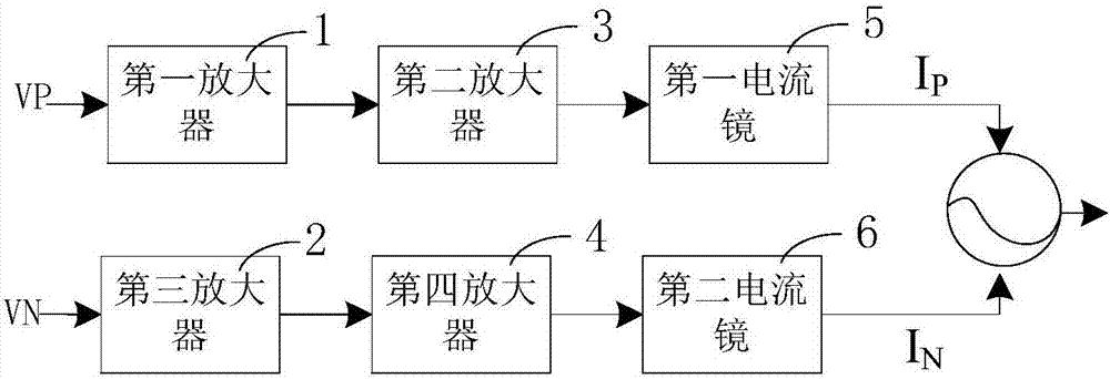
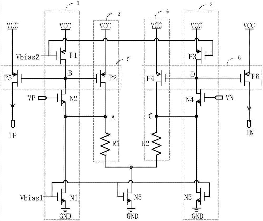
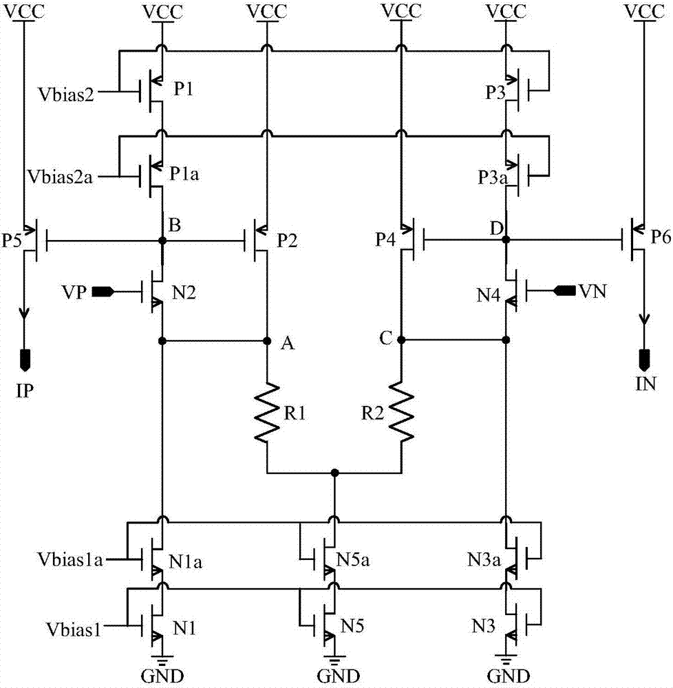
The invention provides a voltage-to-current circuit and device. The voltage-to-current circuit and device comprises a first amplifier, a second amplifier, a third amplifier, a fourth amplifier, a first current mirror and a second current mirror, wherein the first amplifier is used for receiving positive phase voltage signals of differential voltage signals, the second amplifier is connected with the first amplifier to form a first feedback loop and used for converting the positive phase voltage signals into first current signals, the third amplifier is used for receiving negative phase voltage signals of the differential voltage signals, the fourth amplifier is connected with the third amplifier to form a second feedback loop and used for converting the negative phase voltage signals into second current signals, the first current mirror is used for copying the first current signals by the ratio and outputting positive phase currents, and the second current mirror is used for copying second current signals and outputting negative phase currents, wherein the positive phase currents and the negative phase currents are combined into differential currents. A cascade amplifier and a common-source amplifier are adopted to form the feedback loops, the two feedback loops use the same current source, so that output currents are stabilized at a constant value, and linearity and accuracy are improved.

Description

technical field [0001] The invention belongs to the field of integrated circuits, and relates to analog signals or mixed signals, specifically a voltage-to-current circuit and device with high linearity and high input impedance. Background technique [0002] In integrated circuit design, involving high-performance analog / mixed-signal integrated circuits such as digital-to-analog converters, phase-locked loops, and clock duty ratio adjustment circuits, it is necessary to linearly convert voltage signals into current signals. [0003] However, the current voltage-to-current circuit has the disadvantages of complex structure, occupying too much chip area and power consumption. When it is necessary to meet the requirements of a simple structure, it is necessary to introduce too many nonlinear electronic devices, which cannot convert voltage into current. High linearity. [0004] For example, the voltage-controlled oscillator (VCO) in the phase-locked loop circuit usually uses a...

Claims


Application Information

Patent Timeline
Patent Type & Authority Applications(China)
IPC IPC(8): G05F3/26
CPCG05F3/26
Inventor 胡蓉彬王永禄张正平王健安陈光炳付东兵王育新蒋和全胡刚毅
Owner NO 24 RES INST OF CETC
Learn More