
Three-station edge rolling mold for aluminum-based cam shaft sleeve

A camshaft, three-station technology, applied in the field of machinery, can solve the problems of reduced product processing quality and production efficiency, and achieve the effect of avoiding secondary positioning, improving production efficiency and processing quality

Pending Publication Date: 2017-12-15
嘉兴亿腾自动化科技有限公司
View PDF9 Cites 6 Cited by
  • Summary
  • Abstract
  • Description
  • Claims
  • Application Information

AI Technical Summary

Problems solved by technology

[0005] 1. Secondary positioning is required, resulting in a reduction in the processing quality of the product
[0006] 2. Reduced production efficiency

Method used


Image

  • Three-station edge rolling mold for aluminum-based cam shaft sleeve
  • Three-station edge rolling mold for aluminum-based cam shaft sleeve
  • Three-station edge rolling mold for aluminum-based cam shaft sleeve

Examples


Embodiment 1

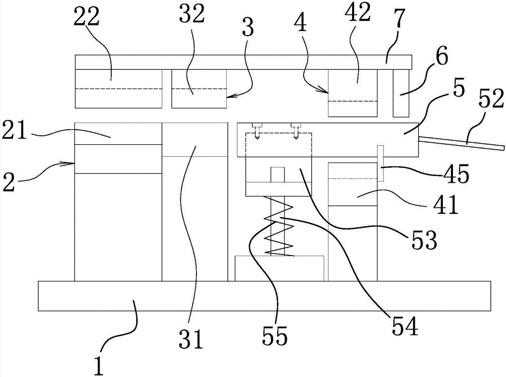
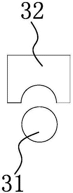
[0034] Such as Figure 1-6 and Figure 8 As shown, the aluminum-based camshaft sleeve three-station rolling mold includes a bottom plate 1, a top plate 7 is arranged on the bottom plate 1, and a primary pre-bending module 2 and a secondary pre-bending module are arranged in sequence on the bottom plate 1. 3 and rolling die set 4.

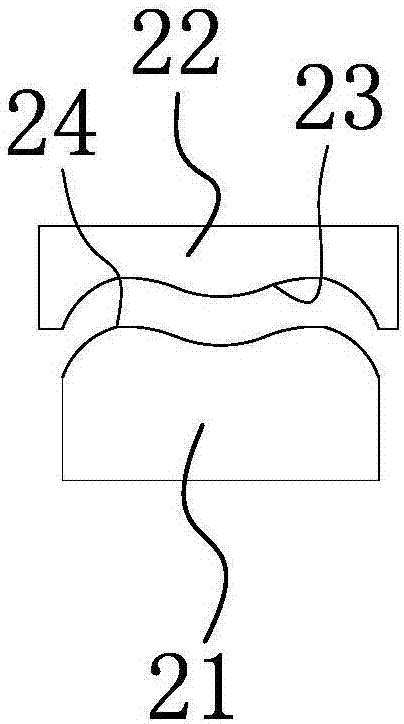
[0035] Specifically, the primary pre-bending die set 2 includes a primary pre-bending punch 21 and a primary pre-bending die 22 located above the primary pre-bending punch 21 , and the primary pre-bending punch 21 and the primary pre-bending die 22 match each other.

[0036] The primary pre-bending punch 21 is fixed on the base plate 1 , and the primary pre-bending die 22 is fixed on the lower surface of the top plate 7 .

[0037] The upper surface of the primary pre-bending punch 21 has an m-forming convex surface 24, and the lower surface of the primary pre-bending die 22 has an m-forming concave surface 23, and the m-forming convex surface 24 a...

Embodiment 2

[0064] The structure and principle of this embodiment are basically the same as those of Embodiment 1, so they will not be repeated here. The difference lies in:

[0065] Such as Figure 7 As shown, the upper surface of the primary pre-bending punch 21 has an inverted U-shaped forming convex surface, and the lower surface of the primary pre-bending die 22 has an inverted U-shaped forming concave surface, and the forming convex surface and the forming concave surface match each other.


PUM


Abstract

The invention belongs to the technical field of machinery, and particularly relates to a three-station edge rolling mold for an aluminum-based cam shaft sleeve. The problems that in the prior arm, the design is unreasonable are solved. The three-station edge rolling mold for the aluminum-based cam shaft sleeve comprises a bottom plate, and a primary pre-bending module, a secondary pre-bending module and an edge rolling module are sequentially arranged on the bottom plate. The mold further comprises a cantilever type hasp compression rod which is arranged between the secondary pre-bending module and the edge rolling module and can rise and fall in the vertical direction, wherein the cantilever type hasp compression rod is horizontally arranged, the suspension end of the cantilever type hasp compression rod extends into the edge rolling module, the end portion of the suspension end of the cantilever type hasp compression rod extends to the outer side of the front end of the edge rolling module, and the cantilever type hasp compression rod is connected with a compression rod lifting driving structure which can drive the cantilever type hasp compression rod to rise and fall in the vertical direction to flatten hasps of a shaft sleeve. The three-station edge rolling mold for the aluminum-based cam shaft sleeve has the advantage of being capable of improving the machining quality and production efficiency.

Description

technical field [0001] The invention belongs to the technical field of machinery, and in particular relates to a three-station rolling die for an aluminum-based camshaft sleeve. Background technique [0002] The rolled shaft sleeve is formed by rolling a piece of steel plate or copper plate. [0003] The current rolling process generally includes three steps of pre-bending, pre-bending U-shaped and rolling. [0004] After the shaft sleeve is rolled into a circle, there is a buckle at the joint. The existing rolling mold cannot simultaneously flatten the buckle after rolling, and the common flattening is to remove the shaft sleeve and go to another Although the flattening process on the equipment can meet the production requirements to a certain extent, this method has at least the following defects: [0005] 1. Secondary positioning is required, resulting in a reduction in the processing quality of the product. [0006] 2. Reduced production efficiency. [0007] Therefor...

Claims


Application Information

Patent Timeline
Patent Type & Authority Applications(China)
IPC IPC(8): B21D37/10B21D5/10B21D5/00B21D39/02
CPCB21D5/00B21D5/10B21D37/10B21D39/02
Inventor 裴向阳肖勇
Owner 嘉兴亿腾自动化科技有限公司
Learn More