
Pipeline reliability testing device
A testing device and reliability technology, applied in the field of testing devices for testing the reliability of pipelines, can solve the problems of high cost and complex reliability testing structure, and achieve the effects of cost saving, simple structure and simple testing structure
- Summary
- Abstract
- Description
- Claims
- Application Information
AI Technical Summary
Problems solved by technology
Method used
Image

Examples
Embodiment Construction
[0023] The specific implementation manner of the present invention will be described below in conjunction with the accompanying drawings.
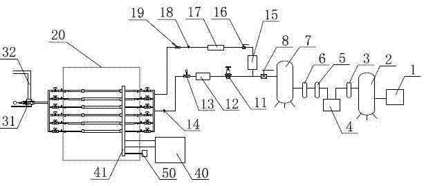
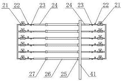
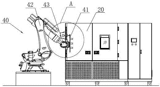
[0024] Such as figure 1 As shown, the pipeline reliability testing device of the present invention includes a drying module, a temperature control module, a testing module and a pulse pressure generator 31 installed in sequence. The air compressor 1 and the first air storage tank 2 are installed in sequence at the air inlet of the drying module, and the air outlet of the first air storage tank 2 passes through the coarse-effect filter 3, the freeze dryer 4, the medium-efficiency filter 5 and the fine-effect filter in sequence. Filter 6, filtered clean gas enters the second gas storage tank 7. The gas outlet end of the second gas storage tank 7 is divided into two paths after passing through the valve 8, and one path is connected to the heating gas path of the temperature control module. and the temperature sensor 14; the other is connect...
PUM
 Abstract
Description
Claims
Application Information