Humidity sensor

A technology of humidity sensor and humidity sensitive capacitor, applied in the sensor field, can solve the problems of no external transmission device, sudden change, unsatisfactory stability, etc., and achieve the effect of reducing data fluctuation and simple structure

Inactive Publication Date: 2017-12-15
温州益禾电子科技有限公司
View PDF6 Cites 3 Cited by
  • Summary
  • Abstract
  • Description
  • Claims
  • Application Information

AI Technical Summary

Problems solved by technology

[0004] The current humidity sensor has only one detection device such as a humidity sensitive capacitor, and the capacitive humidity sensor has quality problems at the same time, and the stability is not ideal. Because the capacitance changes at the unit level, 1%RH is 0.3PF, and the capacitance is small The drift of the %RH value will easily cause a sudden change in the %RH value. Generally, the use of a capacitive humidity sensor in the control field requires careful consideration, and there is no external transmission device, and the user cannot see the measured data remotely.

Method used


Image

  • Humidity sensor

Examples


Embodiment 1

[0031] The humidity sensor is provided with an illumination sensor including a housing, a light guide assembly, a photosensitive assembly, and a signal transmission assembly. The light guide assembly is provided with a cosine corrector, and the cosine corrector is frustum-shaped, and the upper opening is larger than the lower surface. The photosensitive component is provided with a blue filter and a yellow filter, the blue filter is located above the yellow filter, the blue filter is located below the cosine corrector, and the blue filter is located below the cosine corrector. With the yellow filter, the blue light and yellow light can be filtered to increase the accuracy. The signal transmission component is equipped with a silicon blue photovoltaic detector, a photosensitive three-stage tube, a temperature sensitive sensor, and a single-chip microcomputer. The silicon used to detect tiny light The blue photovoltaic detector is located below the yellow filter, and the photosen...

Embodiment 2

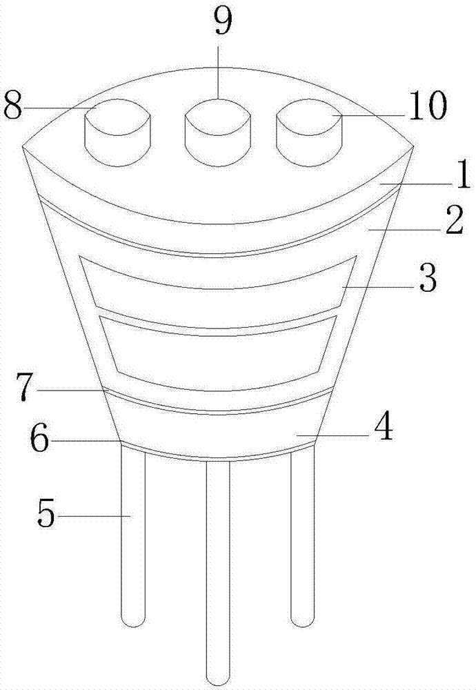
[0035] The two lower electrodes are connected in series with the two capacitors formed by the humidity-sensitive material and the upper electrode. When the ambient humidity changes, the capacitance of the humidity-sensitive capacitor 2 changes accordingly, that is, when the relative humidity increases, the humidity-sensitive capacitor 2 changes accordingly. The capacity increases accordingly, and vice versa decreases (capacity is usually between 48 and 56pf). The conversion circuit of the sensor converts the change of the humidity sensitive capacitance 2 into a change of voltage, corresponding to the change of relative humidity from 0 to 100%RH, the output of the sensor shows a linear change of 0 to 1v, and the data is transmitted to the single chip microcomputer to If the anti-humidity sensitive capacitor 2 breaks down or due to large fluctuations in long-term work, a humidity-sensitive resistor 4 is provided, and the humidity of the electrode gold film of the humidity-sensiti...


PUM


Abstract

The invention discloses a humidity sensor which comprises a detection device, a control device and a transmission device, wherein the detection device comprises a temperature-sensing capacitor, a temperature-sensing resistor and an induction chip; the control device is a single-chip; the transmission device is a wireless transmission device; the temperature-sensing resistor is positioned below the temperature-sensing capacitor; the induction chip is arranged above the temperature-sensing capacitor; the single-chip is arranged above the induction chip; and the wireless transmission device is positioned inside the single-chip. The humidity sensor disclosed by the invention has the obvious advantages that the structure is simple, a humidity-sensing capacitor and a humidity-sensing resistor are capable of simultaneously measuring and reducing data fluctuation caused by instable temperature-sensing capacitance, and detection can be also performed even if one of the humidity-sensing capacitor and the humidity-sensing resistor is damaged. Due to the arrangement of three lamps, a user can clearly know which range the humidity belongs to, the user can be prompted by adopting an audible and visible alarm device, and the user can remotely see the detected data by adopting the wireless transmission device.

Description

technical field [0001] The invention relates to a sensor, in particular to a humidity sensor. Background technique [0002] In the departments of industrial and agricultural production, meteorology, environmental protection, national defense, scientific research, aerospace and other departments, it is often necessary to measure and control the ambient humidity. But among conventional environmental parameters, humidity is the most difficult parameter to measure accurately. The method of measuring humidity with a psychrometer or a hair hygrometer has long been unable to meet the needs of the development of modern science and technology. This is because measuring humidity is much more complicated than measuring temperature. Temperature is an independent measurand, while humidity is affected by other factors (atmospheric pressure, temperature). In addition, the standard of humidity is also a difficult problem. Humidity calibration equipment produced abroad is very expensive. ...

Claims


Application Information

Patent Timeline
Patent Type & Authority Applications(China)
IPC IPC(8): G01N27/22G01N27/12
CPCG01N27/223G01N27/121
Inventor 张益强
Owner 温州益禾电子科技有限公司
Why Eureka
Try Eureka