Broadband resonant cavity antenna with gradient structure

A technology of resonant cavity antenna and gradient structure, applied in the field of resonant cavity antenna, can solve the problems of not fully utilizing the internal space of the resonant cavity antenna, increasing the complexity of antenna design, reducing the radiation efficiency of the antenna, etc., so as to save the design process and reduce the impedance bandwidth. and gain performance impact, simplifying the design approach

Inactive Publication Date: 2017-12-15
NORTHWESTERN POLYTECHNICAL UNIV
View PDF5 Cites 7 Cited by
  • Summary
  • Abstract
  • Description
  • Claims
  • Application Information

AI Technical Summary

Problems solved by technology

[0006] To sum up, the problems existing in the existing technology are: the current method of expanding the gain bandwidth of the resonant cavity antenna is relatively limited in performance improvement, not on

Method used


Image

  • Broadband resonant cavity antenna with gradient structure
  • Broadband resonant cavity antenna with gradient structure
  • Broadband resonant cavity antenna with gradient structure

Examples


Embodiment 1

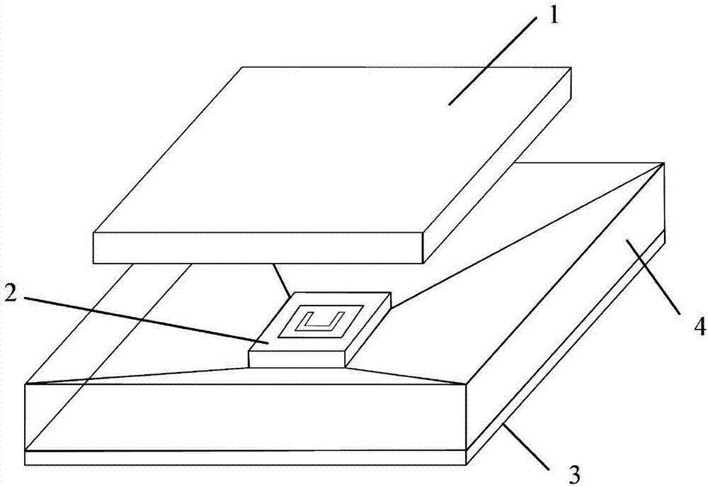
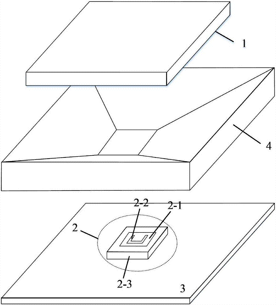
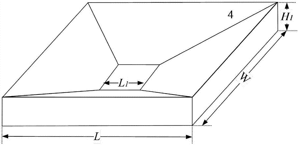
[0051] The 6.5mm thick FR4 plate is used as the dielectric reflection coating 1, and the size is 90mm*90mm; in order to save processing costs and reduce the overall weight of the antenna, an aluminum plate is used as the plate for the floor 3 and the gradient metal wedge structure 4, and other metals can also be used as the plate. The processing plate of the floor 3 and the gradient metal wedge structure 4; the peripheral dimensions of the floor 3 and the gradient metal wedge structure 4 are the same: L=150mm, W=150mm; the thickness of the floor 3 is 1mm; the size of the gradient metal wedge structure 4 is: H 1 =8mm; the height of the cavity formed by the dielectric reflective coating 1 and the floor 3 is 26.5mm; the feed patch 2-1 is printed on a dielectric substrate 2-3 with a thickness of 3.175mm and a relative permittivity of 2.2, and the dielectric The structural parameters of substrate 2-3 are: L 1 = 45mm, W 1 =45mm; the structural parameters of the feed patch 2-1 and t...


PUM


Abstract

The invention belongs to the technical field of resonant cavity antennas and discloses a broadband resonant cavity antenna with a gradient structure. The antenna comprises a dielectric reflective coating layer which is arranged at a position above a metal floor with a distance of a half wavelength. A resonant cavity is formed by the dielectric reflection coating layer and the metal floor, and a U-shaped slot patch antenna is arranged in the cavity. A metal wedge structure with a gradient height is arranged just above the metal floor. The gain bandwidth of the resonant cavity antenna can be significantly improved by the gradient metal wedge structure, and at the same time, the characteristic of a low profile is maintained. The profile height of the antenna is just a half wavelength of a center frequency, by using measures of loading the gradient metal wedge structure and reducing a reflection coating layer aperture size, a phase difference caused by different reflection paths between the floor and the reflection coating layer is compensated, and thus the field distribution in the resonant cavity is more uniform, the gain of the antenna is higher than 15dBi, and a 3dB gain bandwidth is increased from 11.3% to 22.6%.

Description

technical field [0001] The invention belongs to the technical field of resonant cavity antennas, in particular to a tapered structure broadband resonant cavity antenna. Background technique [0002] Current resonant cavity antennas consist of a feed, a floor, and a reflective coating. Resonant cavity antennas belong to the category of narrowband antennas. Since the reflection amplitude and phase of the reflective coating have frequency-selective characteristics, and the resonant height of the resonant cavity is also very sensitive to frequency changes, the gain bandwidth of the resonant cavity antenna is relatively narrow. [0003] At this stage, the means of expanding the gain bandwidth of resonator antennas can be mainly divided into the following two categories: [0004] The first prior art is to optimize the structure of the reflective coating. Using the frequency selective surface with gradually changing unit size as the reflection surface or floor of the resonant ca...

Claims


Application Information

Patent Timeline
IPC IPC(8): H01Q1/38H01Q1/48H01Q1/50H01Q19/10
CPCH01Q1/48H01Q1/38H01Q1/50H01Q19/104
Inventor 冀璐阳张若南李彬
Owner NORTHWESTERN POLYTECHNICAL UNIV
Why Eureka
Try Eureka