

Wireless signal transmitter of ship
A wireless signal and wireless data transmission technology, applied in the field of wireless communication, can solve the problems of poor anti-interference and anti-attenuation, achieve the effect of accurate signal propagation, improve anti-interference ability, and strengthen anti-attenuation
- Summary
- Abstract
- Description
- Claims
- Application Information
AI Technical Summary
Problems solved by technology
Method used
Image

Examples
Embodiment 1
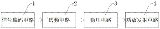
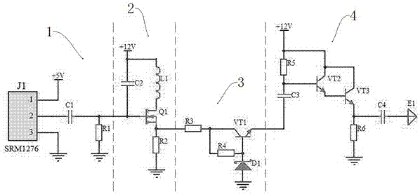
[0017] exist figure 1 , figure 2 Among them, a wireless signal propagator for ships, including a signal encoding circuit 1, a frequency selection circuit 2, a voltage stabilizing circuit 3 and a power amplifier transmitting circuit 4, the signal encoding circuit 1 encodes the signal to be propagated through an encoding chip, and outputs it with a carrier , after being filtered by RC, it is sent to the input end of the frequency selection circuit 2, and the frequency selection circuit 2 generates resonance by the LC to perform frequency selection on the output signal of the signal encoding circuit, and then the voltage is stabilized by the voltage stabilization circuit 3, and then output to the power amplifier transmission circuit 4, The power amplifier transmitting circuit 4 amplifies the power of the output signal of the voltage stabilizing circuit 3, so that the antenna end of the wireless signal propagator has sufficient transmitting power.
[0018] exist figure 2 Among...
Embodiment 2
[0020] Such as figure 2 As shown, on the basis of Embodiment 1, the frequency selection circuit includes a MOS transistor Q1, the gate of the MOS transistor Q1 is connected to one end of the capacitor C2, the drain of the MOS transistor Q1 is connected to one end of the inductor L1, and the other end of the capacitor C2 The other end of the inductor L1 is connected to a +12V power supply, the source of the MOS transistor Q1 is connected to one end of the resistor R2 and one end of the resistor R3, the other end of the resistor R2 is grounded, and the other end of the resistor R3 is connected to the voltage regulator circuit. In this embodiment, the MOS transistor Q1 has good temperature stability characteristics and low amplification noise, and the gate of the MOS transistor Q1 is used to receive the output signal from the signal encoding circuit 1 . In order to further accurately propagate the signal, the capacitor C2 is connected in parallel with the inductor L1 to form res...
Embodiment 3
[0022] Such as figure 2 As shown, on the basis of the second embodiment, the voltage stabilizing circuit 3 includes a resistor R4, a triode VT1 and a voltage stabilizing diode D1, wherein the output signal of the MOS transistor Q1 flows into the collector of the triode VT1 after being divided by the resistor R3, and the other part After being divided by the resistor R4, it flows into the base of the triode VT1 and the cathode of the Zener diode D1, the anode of the Zener diode D1 is grounded, and the emitter of the triode VT1 is output to the input terminal of the transmitter circuit 4 of the power amplifier. In this embodiment, the wireless signal after frequency selection is unstable, and a voltage stabilizing circuit is composed of a resistor R4, a transistor VT1 and a voltage stabilizing diode D1 to effectively stabilize the wireless signal.
PUM
 Abstract
Description
Claims
Application Information