
Pneumatic driven robot tool exchanging device

A technology of tool exchange and pneumatic drive, applied in the direction of manufacturing tools, manipulators, chucks, etc., can solve the problems of complex system structure and control methods, insufficient safety, and poor versatility, and achieve easy disassembly, good safety, and universal good sex effect

Inactive Publication Date: 2017-12-19
CHANGSHA ZHANSHUO XUANXING INFORMATION TECH CO LTD
View PDF4 Cites 7 Cited by
  • Summary
  • Abstract
  • Description
  • Claims
  • Application Information

AI Technical Summary

Problems solved by technology

[0004] According to the search of the existing technology, it is found that the patent "manipulator fixture and tool exchange device in cutting and scribing equipment" (Patent No.: ZL02151074.1) applied by Shanghai Jiaotong University uses a manipulator to grasp the cutting torch and scribing torch , the versatility is not strong, it only meets the needs of the robot for plasma cutting and scribing of marine steel, and the safety is not enough. Once the system is accidentally powered off, the manipulator will suddenly release the tool, causing hazards
The patent "automatic tool exchange interface device" (patent number: ZL200710097421.0) applied by the Fourth Research Institute of the Second Artillery Equipment Research Institute requires both vacuuming to retract the spring pin and compressed air to separate the fixed end from the tool end. The system structure and control methods are relatively complex

Method used


Image

  • Pneumatic driven robot tool exchanging device
  • Pneumatic driven robot tool exchanging device

Examples


Embodiment Construction

[0020] The technical solutions of the present invention will be further described below in conjunction with the accompanying drawings and embodiments.

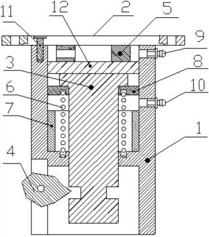
[0021] Such as figure 1 As shown, the robot side module of the present invention is mainly composed of a housing 1, a robot side connecting plate 2, a valve core 3, a cam 4, an upper limit ring 5, a spring 6, a lower limit ring 7, a spring cover plate 8, and the cam retracts compressed air. The interface 9, the cam protruding compressed air interface 10, the countersunk bolt 11, and the valve core piston 12 are composed. The bottom of the inner cavity of the shell 1 supports the spring 6, and the spring 6 covers the spring cover plate 8, the spring cover plate 8 supports the valve core 3, the lower part of the valve core piston 12 is in contact with the top of the valve core 3, and the upper part of the valve core piston 12 is fixed with a circular upper limit Circle 5, robot side connecting plate 2 is fixed with housing 1 wi...


PUM


Abstract

The invention provides a pneumatic driven robot tool exchanging device for automatically exchanging tail end tools by a robot and belongs to the field of automatic mechanical equipment. According to the technical scheme, the invention provides a robot-side module and a tool-side module, wherein the robot-side module comprises a shell, a robot-side connecting plate, a valve core, a cam, an upper limiting ring, a spring, a lower limiting ring, a spring cover plate, a cam withdrawing compressed air port, a cam stretching compressed air port, a countersunk bolt and a valve element piston; the robot-side module can be separated from the tool-side module in the manner of withdrawing the cam under the effect of downward motion of the valve element of the robot-side module under the driving of the compressed air; the robot-side module and the tool-side module can be tightly locked by the cam in the manner of stretching the cam under the effect of upward motion of the valve element of the robot-side module under the driving of the compressed air, so that the purpose of fixedly connecting the robot tail end with the tool can be achieved. The pneumatic driven robot tool exchanging device is capable of realizing the reliable and convenient connection between the robot tail end and the tool, is simple in control mode, has a self-locking function and has ultrahigh safety.

Description

technical field [0001] The invention relates to a robot tool changer, in particular to a pneumatically driven robot tool changer. Background technique [0002] Industrial robots are an integral part of modern manufacturing. Robots are playing an increasingly important role in integrated circuit manufacturing, automotive welding, and automotive assembly. [0003] In the field of robot applications, using relatively general-purpose robots to complete different tasks is a feasible way to reduce costs. For example, in the field of manufacturing and processing, a robot can be used to complete different processes such as cutting, grinding, and welding. In these application fields, a tool exchange device for a robot is needed so that the robot can cooperate with different tools to complete different processes. The part where the robot exchange tool device is connected to the end of the robot is called the "robot side module", and the part that is combined with the tool is called...

Claims


Application Information

Patent Timeline
Patent Type & Authority Applications(China)
IPC IPC(8): B25J15/04
CPCB25J15/04B25J15/0425
Inventor 不公告发明人
Owner CHANGSHA ZHANSHUO XUANXING INFORMATION TECH CO LTD
Learn More