Cutting device for blood vessel plaque

A technology for vascular plaque and cutting device, which is applied to surgical cutting instruments, catheters, balloon catheters, etc., can solve problems such as damage to normal blood vessels, easy disintegration of cutting wires, large external size, etc., to achieve reliable connection methods and avoid cutting Silky slipping and disintegrating effects

Pending Publication Date: 2017-12-22
GUANGDONG BROSMED MEDICAL DEVICE CO LTD
View PDF4 Cites 24 Cited by
  • Summary
  • Abstract
  • Description
  • Claims
  • Application Information

AI Technical Summary

Problems solved by technology

The defect of this kind of catheter is that the bending stress of the annular stent is relatively large, and it is difficult to pass through the tortuous blood vessels, resulting in the inability to complete the operation.
In addition, the above three structures do not have an indicator ring for the position of the cutting wire. The position of the cutting wire cannot be seen under X-rays. The position of the cutting wire can only be guessed based on the position of the balloon developing ring for surgical expansion, which will also lead to co

Method used


Image

  • Cutting device for blood vessel plaque
  • Cutting device for blood vessel plaque
  • Cutting device for blood vessel plaque

Examples


Embodiment 1

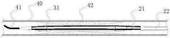
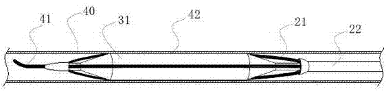
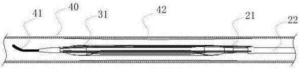
[0050] Such as figure 1 As shown, the vascular plaque cutting device of the present invention is placed in the lesion plaque 42 of the target blood vessel 40 by an interventional department or a radiologist along the guide wire 41 in the percutaneous cavity. On the outer peripheral surface of the balloon 31, the balloon 31 is in an uninflated state and is distributed in a multi-lobed package. Such as figure 2 As shown, when the pressure medium is filled into the balloon, the balloon 31 expands into a columnar shape under the action of internal pressure, and the cutting wire 21 deforms into a spindle shape as the balloon expands, and the cutting wire 21 contacts the vascular plaque 42 at the target blood vessel 40 And cutting into the plaque tears the plaque. Such as image 3 As shown, after repeatedly filling the balloon and observing that the target blood vessel plaque is well cut and expanded, the balloon 31 is suctioned with negative pressure to form a negative pressure...

Embodiment 2

[0054] Such as Figure 15 As shown, this embodiment is consistent with Embodiment 1 except for the design of the push rod, and will not be repeated here.

[0055] Such as Figure 15 As shown, the proximal end of the reinforcing tube 22 is connected to the distal outer tube 13, the reinforcing tube 22 is outside the distal outer tube 13, and the reinforcing tube 22 and the outer tube 13 are clearance fit. The distal cutting marking ring 24 is connected to the distal end 34 of the balloon 31 , and the distance between the proximal cutting marking ring 23 and the proximal cone of the balloon 31 is greater than 5 mm. The proximal end of the balloon 31 is connected to the distal end 11 of the distal outer tube 13, and the connection length is less than 20 mm. There are balloon position indicator rings inside the balloon 31 , including a balloon proximal shoulder indicator ring 32 and a distal shoulder indicator ring 33 . The balloon position indicator ring can be developed under...


PUM


Abstract

The invention discloses a cutting device for a blood vessel plaque. The cutting device comprises a plaque cutting system, a pressurized expansion system and a delivering device, wherein the cutting system comprises a plurality of cutting wires or cutting blades which are connected with a far-end cutting indicating ring and a near-end cutting indicating ring; the pressurized expansion system consists of a balloon and a balloon indicating ring; the delivering device comprises a long and thin hollow near-end pipe body connected with the pressurized expansion system, a stress transition pipe and a pressure connecting seat. The cutting device for the blood vessel plaque, disclosed by the invention, has the following characteristics that the positions of the cutting wires or the cutting blades can be seen in the cutting operation process of the blood vessel plaque, the convenience in operation is realized, and bending of the balloon is avoided; the cutting device can be used for cutting the blood vessel plaque, in particular a heavily-calcified or fibrous plaque at lower pressure without less damage to blood vessels.

Description

technical field [0001] The invention belongs to the technical field of medical instruments, and in particular relates to a blood vessel plaque cutting device that can be used for expanding blood vessel occlusion sites. Background technique [0002] Interventional therapy refers to the use of puncture needles, catheters, and other interventional equipment to insert specific instruments through natural channels or tiny wounds under the guidance and monitoring of digital subtraction angiography, CT, ultrasound, and magnetic resonance imaging equipment. A general term for a series of technologies that are introduced into human diseased parts for minimally invasive treatment. Vascular plaque is the accumulation of fat and cholesterol in arteries, forming atherosclerotic plaques, resulting in narrowing and blocking of arteries. The symptoms of atherosclerosis mainly depend on the degree of vascular disease and ischemia of the affected organs. Aortic atherosclerosis often has no ...

Claims


Application Information

Patent Timeline
IPC IPC(8): A61B17/3207A61B17/00A61M25/10
CPCA61M25/104A61B17/00234A61B17/3207A61B17/320725A61B2017/320741A61M2210/12A61M2210/005A61B2017/22061
Inventor 张志军黄君仪罗锦涛
Owner GUANGDONG BROSMED MEDICAL DEVICE CO LTD
Why Eureka
Try Eureka