Swing arm machine for logistics sorting

An arm crane and logistics technology, which is applied in the direction of conveyor objects, transportation and packaging, etc., can solve the problems of accelerating the aging of synchronous belts, reducing transmission efficiency, and reducing the service life of synchronous belts, so as to prolong the service life, low maintenance costs, and less The effect of energy expenditure

Pending Publication Date: 2017-12-22
SHANGHAI XINBA AUTOMATION TECH CO LTD
View PDF8 Cites 3 Cited by
  • Summary
  • Abstract
  • Description
  • Claims
  • Application Information

AI Technical Summary

Problems solved by technology

[0004] This structure has several major defects: first, the equipment uses two different combinations of deceleration methods, which reduces the overall transmission efficiency; second, because a set of synchronous pulleys are added to the structure, the high-speed rotation of the pulley forms a The "inertial flywheel" effect increases the moment of inertia of the equipment. Since the working state of the equipment requires high-speed start and stop, this will inevitably lead to the instant the equipment stops and starts, and the system needs to consume more energy to overcome the impact caused by the rotation of the synchronous pulley. Inertia torque; Third, the synchronous belt is a rubber product, and it is easy to accelerate the aging of the synchronous belt in the harsh working environment on site, so the service life of the synchronous belt pulley is generally not long; Fourth, the conventional swing arm sorter adopts The number of teeth of the synchronous belt is an integer multiple of the synchronous pulley, so that the force position of the synchronous belt is fixed at several positions on the synchronous belt, and the long-term pulling of a fixed position on the synchronous belt further deteriorates the use of the synchronous belt. conditions, greatly reducing the service life of the synchronous belt; fifth, due to the special working state of the swing arm sorter, when the swing arm is in push-pull reciprocating motion, it only needs to do work when it is pushed out, and when it is returned, the equipment is in no-load state, increasing the reactive power loss of the equipment

Method used


Image

  • Swing arm machine for logistics sorting
  • Swing arm machine for logistics sorting
  • Swing arm machine for logistics sorting

Examples


Embodiment Construction

[0033] The present invention will be described in detail below in conjunction with the accompanying drawings.

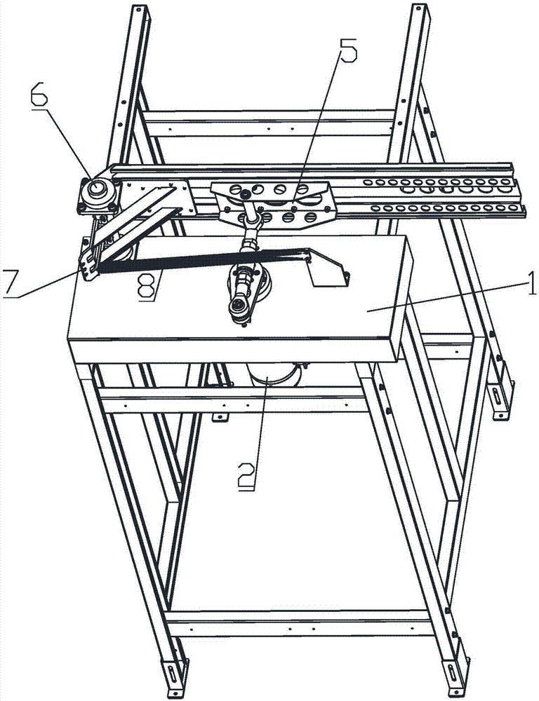
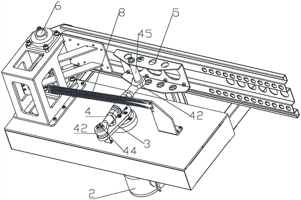
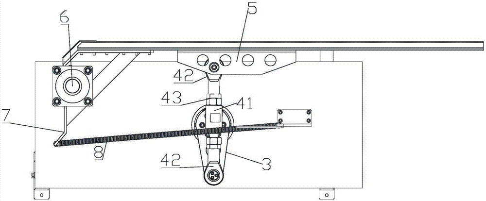
[0034] Such as Figure 1 to Figure 3 As shown, the swing arm machine for logistics sorting in this embodiment includes: a bracket 1, a driving device 2, a crank 3, a connecting rod 4 and a push plate 5, and the driving device 2 is arranged on the bracket 1; 3 can be set on the bracket 1 with one end as the center; the drive device 2 is set to drive the crank 3 to rotate at one end. In this embodiment, the drive device 2 is set at the bottom of the crank 3; the connecting rod 4 It is rotatably connected with the crank 3, and when the crank 3 rotates, it drives the connecting rod 4 to move; the push plate 5 can be arranged with one end as the center, and the connecting rod 4 is connected with the push plate 5, so When the connecting rod 4 is driven by the crank 3 to move, the push plate 5 is rotated. The driving device 2 is a geared motor, the geared motor is provide...


PUM


Abstract

The invention discloses a swing arm machine for logistics sorting. The swing arm machine for logistics sorting comprises a bracket, a driving device, a crankshaft, a connecting rod and a push plate, wherein the driving device is arranged on the bracket; the crankshaft can be rotatably arranged on the bracket by taking one end as a center; the driving device drives one end of the crankshaft to be rotatably arranged; the connecting rod is rotatably connected to the crankshaft, and the crankshaft rotating drives the connecting rod to move; the push plate can be rotatably arranged by taking one end as a center, the connecting rod is connected to the push plate, and the connecting rod is driven by the crankshaft to move, so that the push plate rotates. The swing arm machine for logistics sorting disclosed by the invention is simple in structure, can push parcels to be sorted effectively, and realizes automatic operation.

Description

technical field [0001] The invention relates to a swing arm machine for logistics sorting. Background technique [0002] Logistics sorting is generally divided into two categories: item delivery sorting and item delivery sorting. Distribution and sorting refers to the operation process in which the logistics distribution center quickly and accurately picks up the goods from their storage locations or other locations according to the customer's order requirements or distribution plans, and classifies and concentrates them in a certain way; Sorting refers to the process of sorting items into relevant bins or stacks one by one according to the address written on the cover of the mail (express) and according to the sorting route (that is, the direction) compiled by the company itself. [0003] In the process of logistics sorting, a swing arm mechanism is needed to push the items on the road. For example, Chinese patent CN202609556U discloses a swing arm mechanism of a sorting a...

Claims


Application Information

Patent Timeline
Patent Type & Authority Applications(China)
IPC IPC(8): B65G47/82
CPCB65G47/82
Inventor 胡达理花岳东钱小东
Owner SHANGHAI XINBA AUTOMATION TECH CO LTD
Why Eureka
Try Eureka