
Penetration accelerating device suitable for in-situ leaching of ion-type rare earth mine

An ion-type rare earth and in-situ leaching technology, which is applied in the field of mineral monitoring, can solve problems such as local landslides, easy collapse of hole walls, and collapse of liquid injection hole walls, so as to prevent slope slippage, ensure operation safety, and save operation costs Effect

Active Publication Date: 2017-12-22
JIANGXI UNIV OF SCI & TECH
View PDF8 Cites 0 Cited by
  • Summary
  • Abstract
  • Description
  • Claims
  • Application Information

AI Technical Summary

Problems solved by technology

However, the dense arrangement of liquid injection wells destroys the integrity of the slope, and the shear strength is greatly weakened. With continuous seepage, the liquid injection wells with small spacing are easily connected, causing local landslides
[0014] (2) The leaves rot and block the pores of the injection well
However, as the leaching time goes by, the leaves and weeds are prone to react with the leaching chemical solution, causing the leaves and weeds to rot and form debris. A large amount of debris will easily block the small pores on the wall of the injection hole as the leaching solution flows. , which greatly prevents the seepage of the solution, and has an adverse effect on the in-situ leaching of ion-type rare earth ore bodies
[0016] (3) The wall of the injection hole collapses, resulting in the failure of the injection
[0017] Neither densely arranging the injection wells nor filling the injection wells with leaves can guarantee the stability of the injection holes during the injection process.
The liquid injection shallow well is constructed on the surface and belongs to the strong weathered layer. Long-term liquid injection causes the strength of the soil body on the hole wall to decrease rapidly. Even if the well is filled with leaves and weeds, it is also a flexible material that cannot strengthen the hole wall. Very easy to collapse, making the injection process fail
[0018] (4) The difficulty of construction increases and the operating cost increases
[0021] In the existing technology, the accelerated full infiltration method used in the in-situ leaching of rare earth mines can play a good role in the initial stage of infiltration, but as the infiltration time goes by, problems such as blockage of pore walls and inter-pore connectivity appear, and even induce A series of serious consequences such as the collapse of the liquid injection hole and soil landslides; at the same time, it also increases the difficulty and cost of construction;
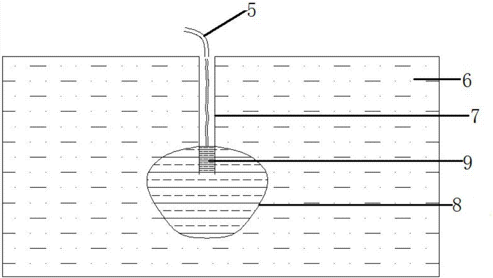
[0022] Due to the liquid injection in the empty hole of the liquid injection well currently used, using Pascal's law, the penetration rate of the leaching liquid in the liquid injection well depends on the pressure of the injected liquid. It can be seen that the deepest part of the liquid injection well has the highest pressure and the fastest penetration speed. The closer the distance to the orifice, the slower the penetration rate, so this method forms a triangular liquid injection area at the bottom of the liquid injection well; it is not conducive to accelerating the full recovery of rare earth resources

Method used


Image

  • Penetration accelerating device suitable for in-situ leaching of ion-type rare earth mine
  • Penetration accelerating device suitable for in-situ leaching of ion-type rare earth mine
  • Penetration accelerating device suitable for in-situ leaching of ion-type rare earth mine

Examples


Embodiment Construction

[0036] In order to make the object, technical solution and advantages of the present invention more clear, the present invention will be further described in detail below in conjunction with the examples. It should be understood that the specific embodiments described here are only used to explain the present invention, not to limit the present invention.

[0037] The invention aims at a series of problems such as uneven infiltration, easy collapse of the liquid injection well, high construction difficulty and high cost in the in-situ leaching process of ionic rare earth, and provides a method that can not only accelerate uniform penetration, but also protect the hole wall of the liquid injection well. device, so as to efficiently and quickly recover rare earth resources and save the construction cost of liquid injection wells.

[0038] The application principle of the present invention will be described in detail below in conjunction with the accompanying drawings.

[0039] ...


PUM


Abstract

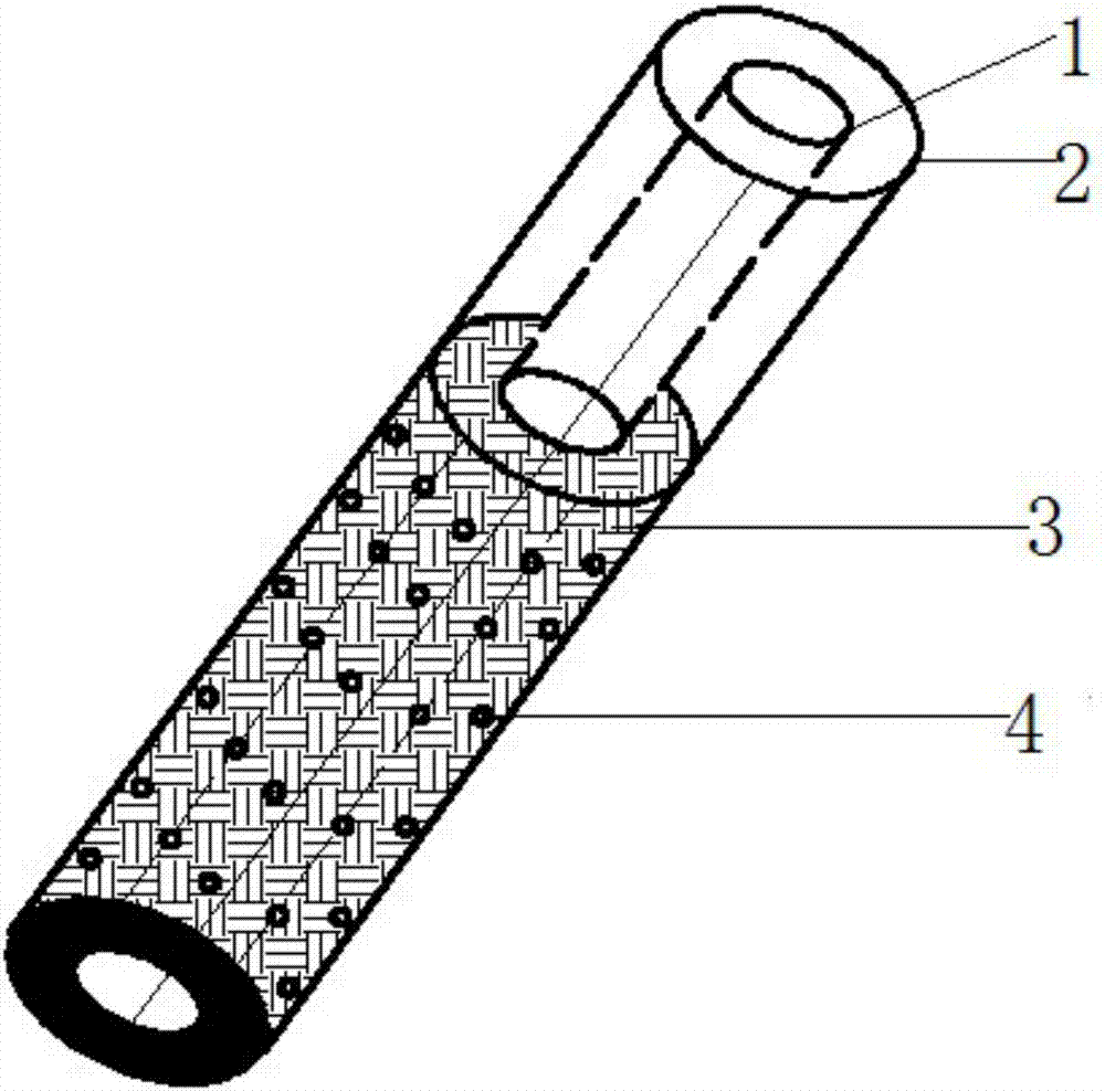
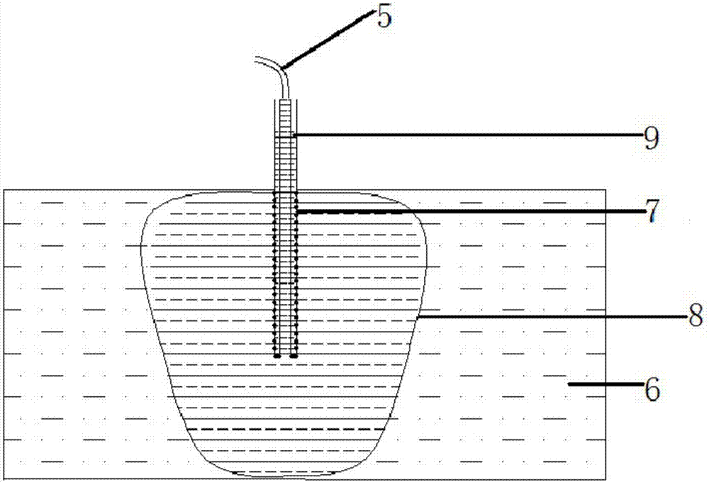
The invention belongs to the technical field of mineral monitoring equipment, and discloses a penetration accelerating device suitable for in-situ leaching of an ion-type rare earth mine. The penetration accelerating device comprises an inner pipe and an outer pipe. A part of a cavity between the inner pipe and the outer pipe is filled with a porous anti-corrosion medium. The bottom of the cavity is sealed, the top of the cavity is open, the inner pipe is transparent up and down, and a plurality of seepage small holes are formed in the portion, as high as filling of the porous anti-corrosion medium, of the outer pipe. Aiming at the technical defects existing at the aspect of in-situ leaching of ion-type rare earth, the penetration accelerating device for in-situ leaching which is high in technological application, good in penetration effect and beneficial for stability of a liquid injection well is put forward. Accelerated sufficient penetration is achieved on the technical theory, the stability of the liquid injection well is ensure at the same time, slope sliding caused by connected collapse of the liquid injection well is prevented, and the operation safety is guaranteed. The penetration accelerating device achieves accelerated even penetration of mineral leaching liquid in the hole walls, and protects the stability of hole walls at the same time, the operation cost is saved, and safe and high-efficiency mineral leaching operation is ensured.

Description

technical field [0001] The invention belongs to the technical field of mineral monitoring, and in particular relates to an accelerated permeation device suitable for in-situ leaching of ionic rare earth mines. Background technique [0002] Ion-adsorption rare earth ores are rare and valuable minerals in the world. Ionic rare earth resources are stored in strong weathered rock formations on the shallow surface. In recent years, the in-situ leaching mining method of ionic rare earths has been popularized to recover resources. The in-situ leaching method is used to implement back mining. This method mainly uses the chemical replacement reaction of the leaching solution in the ore body seepage process to recover rare earth cations. The key to recycling. On the one hand, the leaching liquid must be fully infiltrated in the rare earth ore body. On the other hand, considering that the long-term saturation of the mother liquid in the ore body will induce the risk of landslides, the...

Claims


Application Information

Patent Timeline
Patent Type & Authority Applications(China)
IPC IPC(8): C22B59/00C22B3/02C22B3/04
CPCC22B3/02C22B3/04C22B59/00Y02P10/20
Inventor 王晓军卓毓龙李永欣黄广黎钟文赵奎
Owner JIANGXI UNIV OF SCI & TECH
Learn More