
Push rod controller

A controller and push rod technology, used in construction, door/window fittings, wing fan control mechanisms, etc., to achieve high efficiency, avoid electrical spark problems, and low no-load current.

Pending Publication Date: 2017-12-22
东莞新嘉合科技有限公司
View PDF10 Cites 5 Cited by
  • Summary
  • Abstract
  • Description
  • Claims
  • Application Information

AI Technical Summary

Problems solved by technology

However, the current market lacks a push rod controller that can control permanent magnet brushless DC motors.

Method used


Image

  • Push rod controller
  • Push rod controller
  • Push rod controller

Examples


Embodiment Construction

[0021] In order to facilitate the understanding of those skilled in the art, the present invention will be further described below in conjunction with the embodiments and the drawings, and the content mentioned in the embodiments does not limit the present invention.

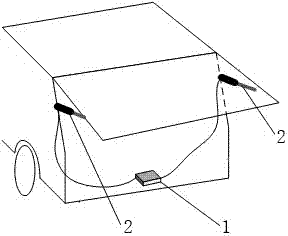
[0022] In this embodiment, the control of the opening and closing of the tailgate of the automobile is implemented as a scene, and the push rod controller is preferably used to control the double push rod device. Such as figure 1 This embodiment provides a dual push rod control system, which includes a controller 1, two push rod devices 2 and a zipper motor installed on the tailgate of an automobile. The controller 1 is electrically connected to the two push rod devices 2, respectively, The zipper motor is electrically connected to the controller 1.

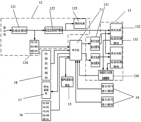
[0023] A putter controller, such as figure 2 , Including single-chip microcomputer (the preferred model is SH79F1611), power module 12, zipper monitoring module 18, re...


PUM


Abstract

The invention relates to the technical field of machine control, in particular to a push rod controller. The push rod controller comprises a single chip microcomputer, a power module, a locking monitoring module, a relay module and at least one brushless motor driving module. The power module, the locking monitoring module, the relay module and the brushless motor driving modules are all electrically connected with the single chip microcomputer. The relay module is used for being electrically connected with a locking motor. When a push rod is started, the locking monitoring module can monitor the state of the locking motor and further transmit the locking motor state information to the single chip microcomputer for treatment. If the locking motor is in a locked state, the single chip microcomputer can control the relay module so as to drive the locking motor to be unlocked. When the single chip microcomputer receives unlocking state signals of the locking motor, the brushless motor driving modules can be controlled by the single chip microcomputer to drive a brushless motor. By adoption of the push rod controller, the push rod with the brushless motor can be well controlled, and the problem of electric sparks caused by contact friction between an electric brush of a brush motor and a commutator is effectively solved.

Description

Technical field [0001] The invention relates to the technical field of machine control, in particular to a push rod controller. Background technique [0002] In the prior art solution, the motor used for the push rod is generally a brushed permanent magnet DC motor, and the corresponding controller is a brushed DC motor controller. Due to the brush commutator structure of the brushed permanent magnet DC motor, friction and contact resistance exist between the brush and the commutator during the operation of the motor, which will cause sparks, large electromagnetic interference, and high no-load current. During the operation of the permanent magnet brushless DC motor, the stator voltage depends on the power element in the control circuit to switch on and off according to a certain law to realize the operation of the rotor. There is no problem of friction between the brush and the commutator. It will produce electric sparks, the no-load current is small, the efficiency is high, an...

Claims


Application Information

Patent Timeline
IPC IPC(8): E05F15/70E05F15/622E05F15/40
CPCE05F15/40E05F15/622E05F15/70E05Y2900/532E05Y2900/548
Inventor 陆民生张杰吴华波黄业伟古振平
Owner 东莞新嘉合科技有限公司
Learn More