
A multi-channel optical fiber synchronous automatic coupling device

A synchronous automatic, coupling device technology, applied in the coupling of optical waveguides, light guides, optics, etc., can solve the problems of difficult mechanical fixation and adjustment of optical devices, poor optical path coupling effect, and high equipment cost, achieving compact structure and power consumption. Small, highly sensitive effect

Active Publication Date: 2019-08-20
黄石晨信光电股份有限公司
View PDF6 Cites 0 Cited by
  • Summary
  • Abstract
  • Description
  • Claims
  • Application Information

AI Technical Summary

Problems solved by technology

[0005] The purpose of the present invention is to solve the problem of high equipment cost and many processes in the passive coupling mode when the current optical device and the transmission optical fiber are coupled. When the active coupling mode is used, the optical device is difficult to mechanically fix and adjust, thereby To solve the problem of poor optical coupling effect, a multi-channel optical fiber synchronous automatic coupling device is provided for this purpose

Method used


Image

  • A multi-channel optical fiber synchronous automatic coupling device
  • A multi-channel optical fiber synchronous automatic coupling device

Examples


Embodiment Construction

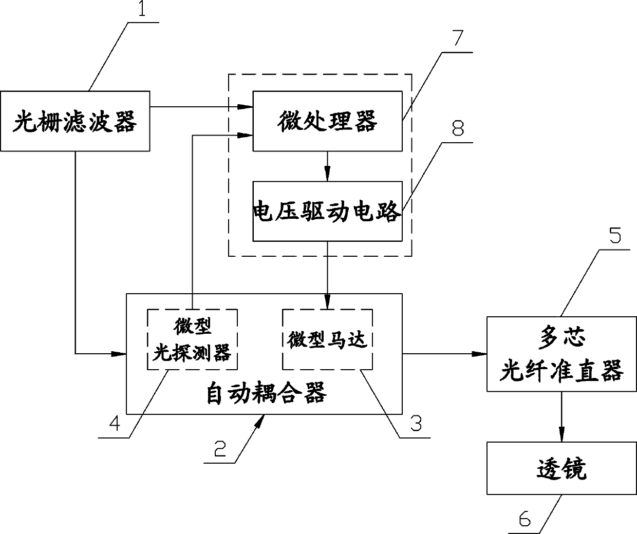
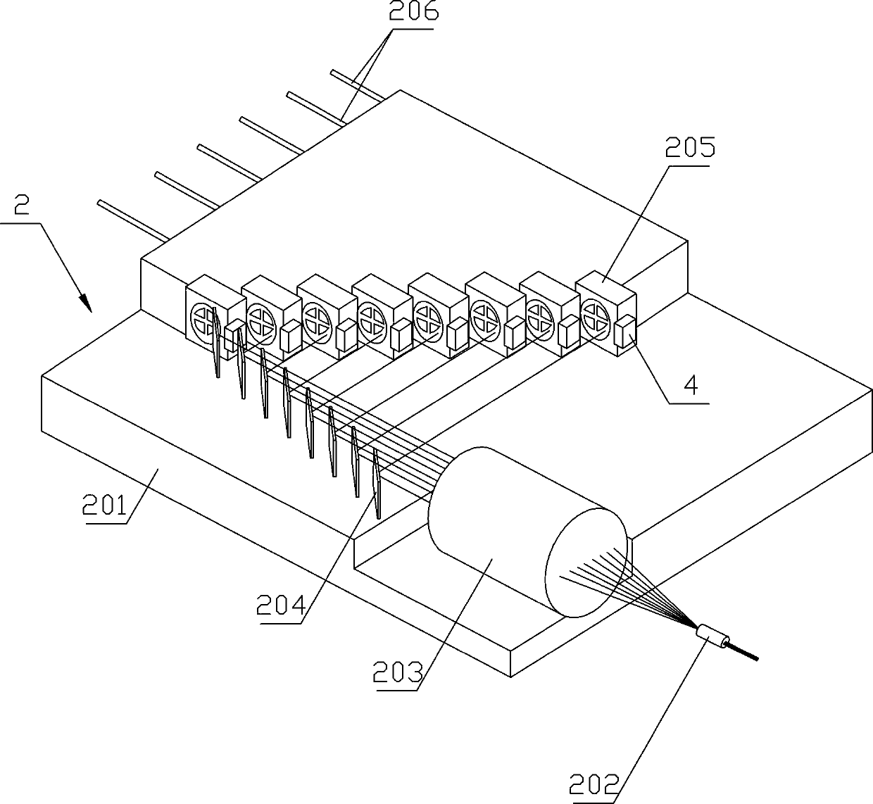
[0023] see Figure 1-2 , a multi-channel optical fiber synchronous automatic coupling device, comprising the following structure:

[0024] - a grating filter 1 for selecting the wavelength of the output light wave;

[0025] - an automatic coupler 2 for automatically coupling the light waves output by the grating filter 1, the automatic coupler 2 includes a coaxially arranged optical beam splitter 202 and an optical beam combiner 203 integrated on the PCB board 201 and several groups of two Two oppositely arranged prisms 204 and MEMS reflectors 205 are respectively arranged in a stepped structure, the prisms 204 and MEMS reflectors 205 are arranged in a figure-eight structure, and the distance between each set of oppositely arranged prisms 204 and MEMS reflectors 205 The vertical distance is 5 mm to 50 mm; the optical beam splitter 202 decomposes the light wave delivered from the grating filter 1 into multiple light beams according to the wavelength, and the multiple light bea...


PUM


Abstract

The present invention relates to an optical fiber light path coupling technology field, in particular to a multi-optical fiber synchronous and automatic coupling device. The multi-optical fiber synchronous and automatic coupling device comprises a grating filter used for selecting the wavelengths of the outputted optical waves, an automatic coupler used for automatically coupling the optical waves outputted by the grating filter, a control device matching the automatic coupler and adjusting the light paths automatically, a multi-core optical fiber collimator used for transforming the light outputted by the automatic coupler into the parallel light and a lens used for focusing the parallel light outputted by the multi-core optical fiber collimator on a multi-core optical fiber, wherein the automatic coupler comprises a light beam splitter, a light beam combiner and multiple sets of prisms and MEMS reflectors which are integrated on a PCB, each prism and each reflector are arranged relatively, and the prisms and the reflectors are arranged respectively into the stepped structures. The multi-optical fiber synchronous and automatic coupling device of the present invention is compact in structure, low in cost and small in loss, can be integrated on the PCB conveniently and firmly, realizes the efficient, automatic and synchronous coupling of a high-speed optical assembly and the multi-core optical fiber, and guarantees the stability and the reliability of the light path synchronous coupling.

Description

technical field [0001] The invention relates to the technical field of optical fiber optical path coupling, in particular to a multi-channel optical fiber synchronous automatic coupling device. Background technique [0002] At present, as a core component in the field of optical communication, the coupling effect of optical integrated components and optical fibers in optical modules greatly affects the strength and quality of optical signals, and thus becomes one of the key factors affecting information transmission. [0003] At present, there are two methods of optical coupling between optical devices and transmission fibers in optical modules: active coupling and passive coupling. The process of the active coupling method is: fix the laser as the light source on the PCB board, then control the laser to emit light, use the coupler adjustment to change the spatial position of the optical lens module used as the optical transmission path device, and detect the light passing t...

Claims


Application Information

Patent Timeline
Patent Type & Authority Patents(China)
IPC IPC(8): G02B6/293G02B6/34G02B26/08
Inventor 叶苍竹江涛熊辉官守军
Owner 黄石晨信光电股份有限公司
Learn More