
A kind of heat dissipation method for heat dissipation device of communication equipment

A heat dissipation method and technology of a heat dissipation device, which are applied in the direction of temperature control, measurement device, and electrical equipment structural components using digital devices, can solve the problem of low heat dissipation efficiency, inability to meet the heat dissipation requirements of communication equipment, and inability to install high-power heat dissipation and cooling equipment and other issues, to achieve reliable heat dissipation, maximize heat exchange efficiency, and improve service life.

Active Publication Date: 2020-05-22
STATE GRID ZHEJIANG HANGZHOU YUHANG POWER SUPPLY +2
View PDF9 Cites 0 Cited by
  • Summary
  • Abstract
  • Description
  • Claims
  • Application Information

AI Technical Summary

Problems solved by technology

[0002] Under high temperature conditions in summer, communication equipment needs to be installed with an air temperature regulator to enable the communication equipment to dissipate heat in time. Closed places, these places are limited by the space environment and cannot be installed with ordinary high-power cooling devices, so usually a radiator is installed on the communication equipment, and a fan is installed on the radiator, and the airflow generated by the fan accelerates the heat dissipation of the radiator. However, this cooling method The heat dissipation efficiency is low, which cannot meet the heat dissipation requirements of communication equipment

Method used


Image

  • A kind of heat dissipation method for heat dissipation device of communication equipment
  • A kind of heat dissipation method for heat dissipation device of communication equipment
  • A kind of heat dissipation method for heat dissipation device of communication equipment

Examples


Embodiment 1

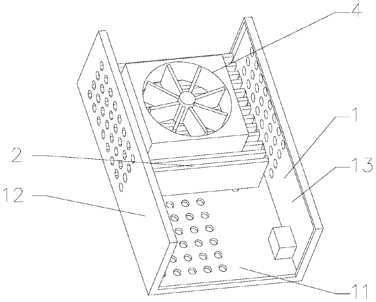
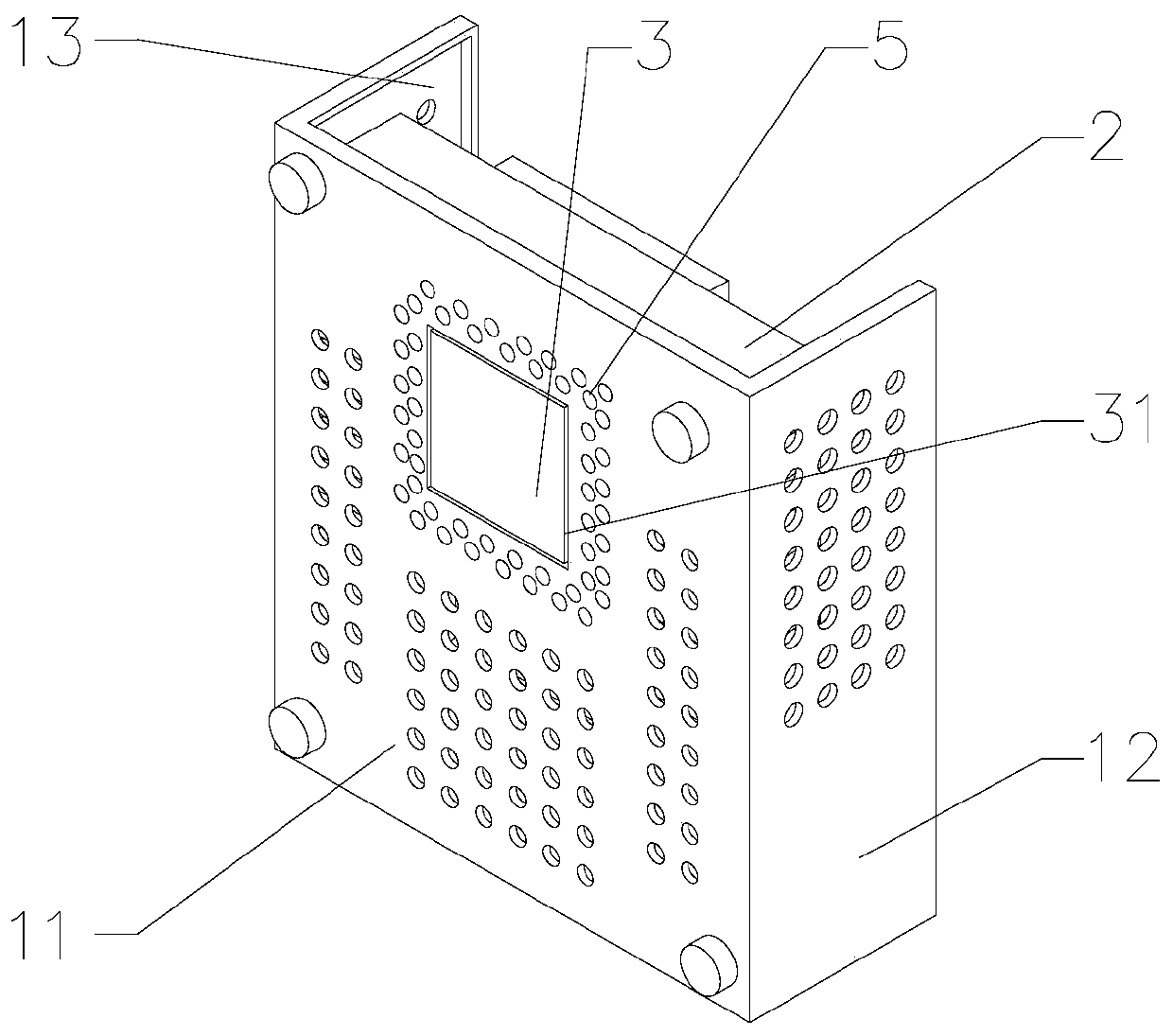
[0040] Such as Figures 1 to 3As shown, the present invention provides a heat dissipation method for a heat dissipation device of communication equipment. The heat dissipation device includes a housing 1, a radiator 2, a semiconductor cooling chip 3 and a fan 4. The semiconductor cooling chip 3 has low power consumption and low noise. It is reliable in use and is very suitable for narrow spaces. The semiconductor cooling chip 3 includes a cooling surface 31 and a heat dissipation surface 32. Both the cooling surface 31 and the heat dissipation surface 32 are coated with heat-conducting silicone grease. The housing 1 includes a main end surface 11, a first end surface 12 and The second end face 13, the first end face 12 and the second end face 13 are arranged on the two ends of the main end face 11, the main end face 11 and the first end face 12, the second end face 13 are integrally arranged and are "Π" type, and the semiconductor refrigeration sheet 3 is inlaid On the main en...

Embodiment 2

[0047] Such as Figures 4 to 6 As shown, the main difference between this embodiment and Embodiment 1 is that this embodiment adds a temperature detection step, a temperature display step and a setting step.

[0048] The heat dissipation device also includes a temperature controller 6 and an LED display 7. The temperature controller 6 includes a temperature control probe 61, an MCU and a setting button 62. The temperature control probe 61 is provided with a temperature sensor for measuring the surface temperature of the communication device. The temperature control probe 61 is connected with MCU by wire, MCU is connected with semiconductor refrigeration sheet 3 by wire, preset temperature is set in MCU, setting button 63 is connected with MCU by wire and can set preset temperature, LED display 7 and MCU are connected by wire It is connected and can display the surface temperature of communication equipment in real time.

[0049] The cooling method of this embodiment includes ...

Embodiment 3

[0057] Such as Figure 7 As shown, the main difference between the present embodiment and the second embodiment is that an adjustment step is added in the present embodiment.

[0058] The heat dissipation device also includes a regulating switch, and the regulating switch is connected with the semiconductor refrigeration sheet through wires.

[0059] The cooling method of this embodiment includes the following steps:

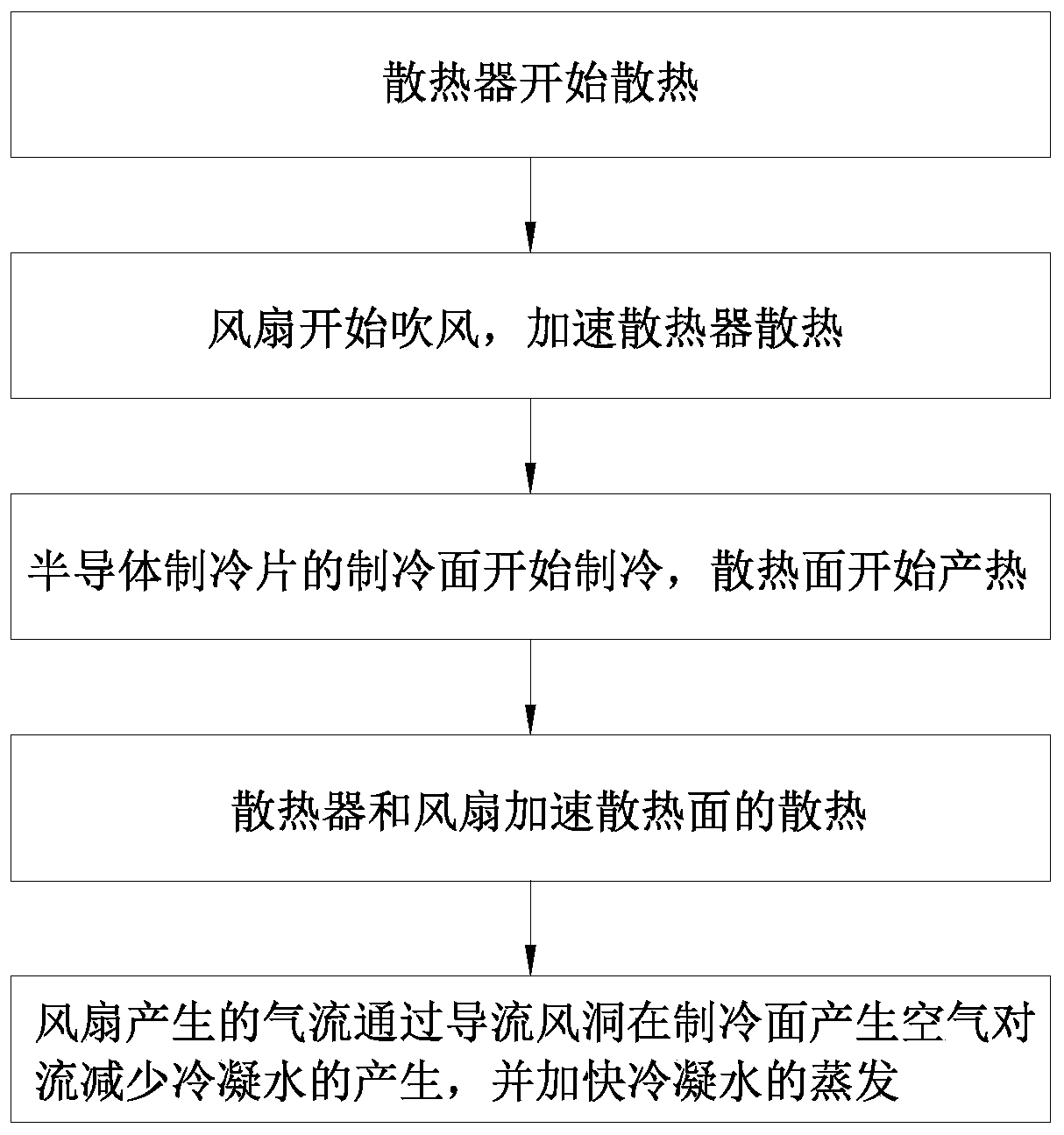
[0060] Preliminary heat dissipation steps: the radiator starts to work, the radiator dissipates the heat transferred from the communication equipment, the fan starts to work, and the fan provides sufficient airflow to the radiator to form air convection around the radiator to speed up the heat dissipation of the radiator.

[0061] Adjustment step: adjust the cooling power of the semiconductor refrigeration sheet in the cooling step by adjusting the switch. This step enables the cooling power of the semiconductor refrigerating sheet to be adjusted according to ...


PUM


Abstract

The present invention provides a heat dissipation method for a heat dissipation device of a communication device. The heat dissipation method includes at least the following steps: a preliminary heat dissipation step: the radiator starts to work, the radiator dissipates the heat transferred from the communication device, and the fan starts to work. The fan provides sufficient airflow to the radiator to form air convection around the radiator to speed up the heat dissipation of the radiator; cooling step: the semiconductor cooling sheet works to reduce the temperature near the cooling surface of the semiconductor cooling sheet; condensed water treatment step: the airflow generated by the fan passes through The diversion wind tunnel conducts air convection heat dissipation on the cooling surface of the semiconductor refrigeration sheet to reduce the condensed water generated by the operation of the semiconductor refrigeration sheet and accelerate the evaporation of the condensed water. Through the preliminary heat dissipation steps, cooling steps and condensed water treatment steps, the heat dissipation is improved. The heat dissipation efficiency of the device, and ensure that the communication equipment will not be affected by condensed water.

Description

technical field [0001] The invention relates to a heat dissipation method of a heat dissipation device, in particular to a heat dissipation method for a heat dissipation device of communication equipment. Background technique [0002] Under high temperature conditions in summer, communication equipment needs to be installed with an air temperature regulator to enable the communication equipment to dissipate heat in time. Closed places, these places are limited by the space environment and cannot be installed with ordinary high-power cooling devices, so usually a radiator is installed on the communication equipment, and a fan is installed on the radiator, and the airflow generated by the fan accelerates the heat dissipation of the radiator. However, this cooling method The heat dissipation efficiency is low, which cannot meet the heat dissipation requirements of communication equipment. Contents of the invention [0003] The purpose of the present invention is to provide a...

Claims


Application Information

Patent Timeline
Patent Type & Authority Patents(China)
IPC IPC(8): H05K7/20G05D23/19G01K1/02G01K13/00
CPCH05K7/20145H05K7/20172H05K7/20209H05K7/2039G05D23/1917G01K1/02G01K13/00
Inventor 丁力邵炜平沈文佳屠永伟姚海燕胡晓琴包拯民沈艳婷卢科帆
Owner STATE GRID ZHEJIANG HANGZHOU YUHANG POWER SUPPLY
Learn More