A forming device for aluminum parts of automobile brakes

A molding device and brake technology, which is applied to casting molding equipment, cores, casting molds, etc., can solve the problems of low production efficiency, easily damaged sand boxes, and many manpower, and achieve high processing efficiency, reduced handling, and simple operation. Effect

Active Publication Date: 2019-02-22
芜湖市云峰铸造有限责任公司
View PDF7 Cites 1 Cited by
  • Summary
  • Abstract
  • Description
  • Claims
  • Application Information

AI Technical Summary

Problems solved by technology

[0003] The existing casting process is to divide the model consistent with the outer contour of the part into two parts, each placed on a workbench, each half of the model can be lifted and lowered on the workbench, and the sand box is placed on each workbench , then raise the model, fill in the molding sand and compact it, after the molding is finished, lower the model, the middle of the two sand boxes will form half a mold cavity, and then make the inner cavity of the workpiece, that is, make a solid core, and then put into the mold cavity formed by two sandboxes, and inject the molten metal into the mold cavity. The gap between the mold cavity and the inner core is the pouring cavity of the workpiece. The molten metal enters the pouring cavity and cools to form a casting. The follow-up surface treatment is enough. This process requires at least two workbenches, and the fit between the sand boxes needs to be moved manually. Many, low production efficiency

Method used


Image

  • A forming device for aluminum parts of automobile brakes
  • A forming device for aluminum parts of automobile brakes
  • A forming device for aluminum parts of automobile brakes

Examples


Embodiment Construction

[0016] Preferred embodiments of the present invention will be described in detail below in conjunction with the accompanying drawings.

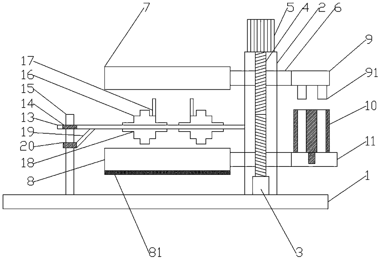
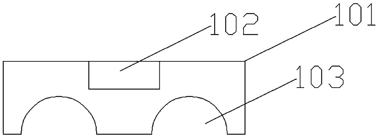
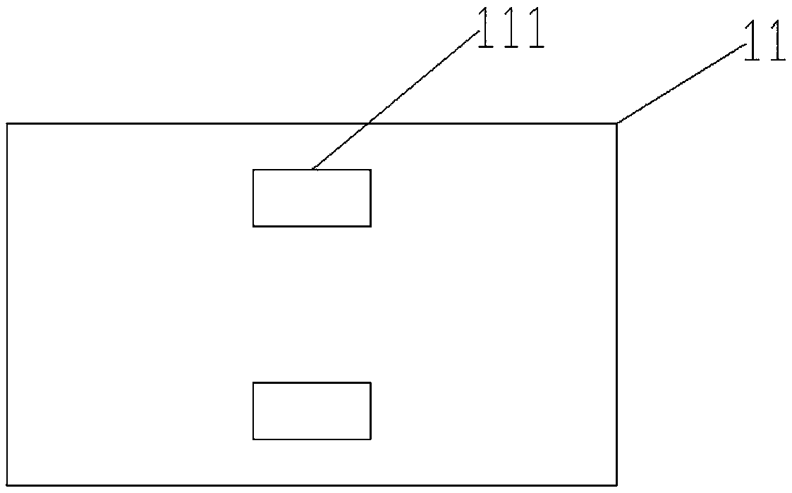
[0017] Figure 1-4 Show the specific embodiment of the present invention: a kind of automobile brake aluminum parts forming device, comprise base 1, described base 1 is provided with strut 15 and support 2, and described strut 15 is provided with bearing 14, so The outside of the bearing 14 is sleeved with a partition plate 13, the end of the partition plate 13 away from the pole is provided with a limit plate 12, the upper end of the partition plate 13 is provided with an upper mold 16, and the upper mold 16 A pouring pipe 17 is provided, a lower mold 18 is provided at the lower end of the partition plate 13, a limit plate 221 is provided on the side of the support 2, a two-way screw rod 4 is arranged inside the support 2, and the two-way screw rod 4 The bottom is provided with a fixed seat 3, and the upper end of the support 2 is provided ...


PUM


Abstract

The invention discloses a vehicle brake aluminum part molding device. The device comprises a base; the base is provided with a support rod and a bracket; the support rod is provided with a bearing 1; a separation plate sleeves the bearing 1; a limiting plate 1 is arranged at the front end of the separation plate; an upper model is arranged at the upper end of the separation plate, and is provided with a pouring pipe; a lower model is arranged at the lower end of the separation plate; a limiting plate 2 is arranged on the side surface of the bracket; a two-way lead screw is arranged in the bracket; a fixed base is arranged at the bottom of the two-way lead screw; a stepper motor is arranged at the upper end of the bracket; a main shaft of the stepper motor is connected with the two-way lead screw; nut bases are respectively arranged at two ends of the two-way lead screw; an upper sand box and an upper support base are respectively arranged at two ends of the nut base at the upper end; a pressing column is arranged at the bottom of the upper support base; a lower sand box and a lower support base are respectively arranged at two ends of the nut base at the lower end; a seepage plate is arranged at the bottom of the lower sand box; and a molding core box is arranged at the upper end of the lower support base. The device is high in machining efficiency, low in production error, simple in operation and excellent in economic benefit.

Description

technical field [0001] The invention relates to the field of sand casting, in particular to a molding device for aluminum parts of automobile brakes. Background technique [0002] Sand casting refers to the casting method of producing castings in sand molds. Steel, iron and most non-ferrous alloy castings can be obtained by sand casting methods. Because the molding materials used in sand casting are cheap and easy to obtain, the casting molds are easy to manufacture. It can be adapted to piece production, batch production and mass production. It has been the basic process in casting production for a long time. [0003] The existing casting process is to divide the model consistent with the outer contour of the part into two parts, each placed on a workbench, each half of the model can be lifted and lowered on the workbench, and the sand box is placed on each workbench , then raise the model, fill in the molding sand and compact it, after the molding is finished, lower the m...

Claims


Application Information

Patent Timeline
Patent Type & Authority Patents(China)
IPC IPC(8): B22C9/22B22C15/06B22C9/12
CPCB22C9/12B22C9/22B22C15/06
Inventor 吴云锋
Owner 芜湖市云峰铸造有限责任公司
Why Eureka
Try Eureka