Water-erosion-preventing turbine blade

A steam turbine blade and blade technology, applied in the directions of blade support elements, mechanical equipment, engine elements, etc., can solve problems such as affecting the service life of the blades, and the blades are easily eroded by water droplets, so as to increase the utilization rate, improve the dehumidification performance, and avoid the The effect of water drop erosion

Inactive Publication Date: 2017-12-29
南京赛达科技有限公司
View PDF0 Cites 1 Cited by
  • Summary
  • Abstract
  • Description
  • Claims
  • Application Information

AI Technical Summary

Problems solved by technology

When the steam turbine is working, high-temperature and high-pressure steam acts on the blades. When the high-temperature steam meets the low-temperature blades, it liquefies and produces water droplets. The blades are easily eroded by water droplets for a long time, which affects the service life of the blades.

Method used


Image

  • Water-erosion-preventing turbine blade
  • Water-erosion-preventing turbine blade
  • Water-erosion-preventing turbine blade

Examples


Embodiment 1

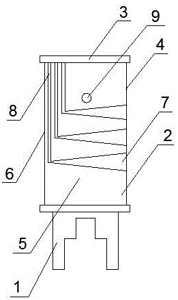
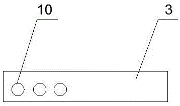
[0033] An anti-corrosion steam turbine blade provided in this embodiment has a structure such as figure 1 As shown, it includes the blade root 1, the blade shape 2 and the blade crown 3, the blade root 1, the blade shape 2, and the blade crown 3 are connected in sequence, the blade root 1 is a fork-shaped blade root 1, and the blade shape 2 includes the intake edge 4, the inner The arc 5, the air outlet edge 6 and the outer arc, the middle and upper part of the airfoil 2 are provided with tension holes 9, and the airfoil 2 is provided with an air guide groove 7 and a dehumidification groove 8,

[0034] There are at least two air guide grooves 7, and the air guide grooves 7 are all parallel to the air outlet edge 6, and the width of the air guide groove 7 gradually narrows from the air inlet edge 4 to the air outlet edge 6. One end of the air guide groove 7 is located at the inlet side 4, the air guide groove 7 is from the air inlet side 4 to the air outlet side 6,

[0035] On...

Embodiment 2

[0047] An anti-corrosion steam turbine blade provided in this embodiment has a structure such as figure 1 As shown, it includes the blade root 1, the blade shape 2 and the blade crown 3, the blade root 1, the blade shape 2, and the blade crown 3 are connected in sequence, the blade root 1 is a fork-shaped blade root 1, and the blade shape 2 includes the intake edge 4, the inner The arc 5, the air outlet edge 6 and the outer arc, the middle and upper part of the airfoil 2 are provided with tension holes 9, and the airfoil 2 is provided with an air guide groove 7 and a dehumidification groove 8,

[0048] There are at least two air guide grooves 7, and the air guide grooves 7 are all parallel to the air outlet edge 6, and the width of the air guide groove 7 gradually narrows from the air inlet edge 4 to the air outlet edge 6. One end of the air guide groove 7 is located at the inlet side 4, the air guide groove 7 is from the air inlet side 4 to the air outlet side 6,

[0049] On...

Embodiment 3

[0061] An anti-corrosion steam turbine blade provided in this embodiment has a structure such as figure 1 As shown, it includes the blade root 1, the blade shape 2 and the blade crown 3, the blade root 1, the blade shape 2, and the blade crown 3 are connected in sequence, the blade root 1 is a fork-shaped blade root 1, and the blade shape 2 includes the intake edge 4, the inner The arc 5, the air outlet edge 6 and the outer arc, the middle and upper part of the airfoil 2 are provided with tension holes 9, and the airfoil 2 is provided with an air guide groove 7 and a dehumidification groove 8,

[0062] There are at least two air guide grooves 7, and the air guide grooves 7 are all parallel to the air outlet edge 6, and the width of the air guide groove 7 gradually narrows from the air inlet edge 4 to the air outlet edge 6. One end of the air guide groove 7 is located at the inlet side 4, the air guide groove 7 is from the air inlet side 4 to the air outlet side 6,

[0063] On...


PUM


Abstract

The invention discloses an anti-corrosion steam turbine blade, which includes a blade root, a blade shape and a blade crown, and the blade root, the blade shape, and the blade crown are connected in sequence, and the blade shape includes an air inlet edge, an inner arc, an air outlet edge and an outer edge. The air guide groove and the dehumidification groove are arranged on the airfoil, one end of the air guide groove is located on the air inlet side, and the air guide groove is from the air inlet side to the air outlet side, and one end of the dehumidification groove is located between the blade shape and the air outlet side. At the joint of the leaf crown, the dehumidification tank is close to the air outlet edge, the dehumidification tank is from the leaf crown to the blade root, the remote end of the air guide groove communicates with the end of the dehumidification tank, and the dehumidification tank on the leaf crown corresponds to A through hole is opened at the end of the groove. In the anti-corrosion steam turbine blade provided by the invention, the water droplets produced by the liquefaction of high-temperature steam are thrown out from the through hole on the blade crown along the dehumidification tank, so as to prevent the water droplets from being located on the blade shape for a long time to cause the blades to be eroded by the water droplets.

Description

technical field [0001] The invention relates to the technical field of power generation equipment, in particular to an anti-corrosion steam turbine blade. Background technique [0002] A steam turbine is a rotary power machine that converts the energy of steam into mechanical work. It is also called a steam turbine. It is mainly used as a prime mover for power generation. The exhaust steam or intermediate extraction steam of the steam turbine can be used to meet the heating needs of production and life. [0003] The steam turbine blade is a rotating fluid power machine, which directly transforms the thermal energy of steam or gas into mechanical energy, and the blade is the "heart" of the steam turbine, which is an extremely important part of the steam turbine. When the steam turbine is working, the high-temperature and high-pressure steam acts on the blades. When the high-temperature steam meets the low-temperature blades, it liquefies and produces water droplets. The blad...

Claims


Application Information

Patent Timeline
Patent Type & Authority Applications(China)
IPC IPC(8): F01D5/14F01D5/30F01D5/28B23P15/02C22C38/02C22C38/44C22C38/46C22C38/50C22C38/48C22C38/42C22C38/06C21D1/18C21D9/00C25F3/06
CPCF01D5/147B23P15/02C21D1/18C21D9/0068C22C38/005C22C38/02C22C38/06C22C38/42C22C38/44C22C38/46C22C38/48C22C38/50C25F3/06F01D5/286F01D5/30
Inventor 刘达王河平宗国翼
Owner 南京赛达科技有限公司
Why Eureka
Try Eureka