System and method for measuring scale amount of furnace tube of boiler of thermal power plant

A boiler tube and measuring system technology, applied in boiler cleaning devices, material electrochemical variables, boiler working status indication, etc., can solve the problem of difficult boiler tube cleaning, low measurement results, and increased matrix metal corrosion loss And other issues

Pending Publication Date: 2017-12-29
DATANG DONGBEI ELECTRIC POWER TESTING & RES INST
View PDF7 Cites 1 Cited by
  • Summary
  • Abstract
  • Description
  • Claims
  • Application Information

AI Technical Summary

Problems solved by technology

[0002] The determination of the chemical cleaning interval of the thermal power plant boiler and the evaluation of the boiler water treatment and water chemical operation mode are based on the amount of sediment on the inner surface of the boiler tube (g / m 2 ) or fouling rate (g / (m 2 · a)) is the judgment standard, and the scale amount measured by the chemical determination method stipulated by the industry standard currently adopted is only the average value of the scale amount on the fire side and the back fire side of the furnace tube, and the measurement result is usually low
In addition, due to the higher the boiler pressure, the harder the scale and the stronger the adhesion to the inner wall of the tube, it is difficult to completely remove the scale from the boiler tube even if the cleaning time is prolonged by using the usual chemical determination method, or because the cleaning time is too long Long and increase the corrosion loss of the base metal, even if the blank correction method is used, it will still cause a large measurement error

Method used


Image

  • System and method for measuring scale amount of furnace tube of boiler of thermal power plant

Examples


Embodiment Construction

[0024] The specific embodiments of the present invention will be described in further detail below in conjunction with the drawings and embodiments. The following examples are used to illustrate the present invention, but not to limit the scope of the present invention.

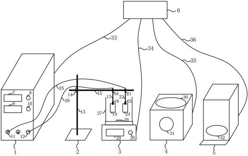
[0025] Participate figure 1 As shown, this embodiment provides a thermal power plant boiler furnace tube scale measurement system, which includes: a direct current electrolysis instrument 1, an experimental support 2, a magnetic stirring electrolytic cell 3, an ultrasonic cleaner 4, and an electronic balance with a precision of 1 / 10 5 and AC 220V 50Hz power supply 6.

[0026] The DC electrolysis instrument 1 includes: a DC voltage display screen 7, a DC voltage adjustment knob 8, a current density display screen 9, a current density adjustment knob 10, an electrolysis instrument positive electrode 11, and an electrolysis instrument negative electrode 12.

[0027] The experimental support 2 includes a vertical supp...


PUM


Abstract

The invention relates to a system and a method for measuring a scale amount of a furnace tube of a boiler of a thermal power plant, wherein the system comprises an electrolytic stripping and descaling device, an ultrasonic cleaner for degreasing the furnace tube of the boiler before and after descaling and an electronic scale for weighing the masses of the furnace tube of the boiler before and after descaling; the electrolytic stripping and descaling device comprises a direct current electrolyser and an electrolytic tank accommodating an electrolytic stripping agent; the direct current electrolyser comprises a cathode and an anode which are separately connected to a platinum electrode and the furnace tube of the boiler; the platinum electrode and the furnace tube of the boiler are arranged in the electrolytic tank; direct current electrolysis is performed under the action of the electrolytic stripping agent to strip scales on the furnace tube of the boiler. The system provided by the invention has the technical effects of being high in descaling speed, short in consumed time and low in blank wastage of a matrix metal; damage on the matrix metal of the furnace tube is very small and blank correction is not performed commonly; the matrix can keep the original shape of the furnace tube under scales; and the system and method are quite beneficial for observing the corrosive shape of the metal under the scales of the furnace tube of the boiler.

Description

Technical field [0001] The invention belongs to the technical field of boiler tube scale measurement in thermal power plants, and particularly relates to a system and method for measuring boiler tube scale in thermal power plants. Background technique [0002] The determination of the chemical cleaning interval of thermal power plant boilers and the evaluation of boiler water treatment and water chemical operation methods are all based on the amount of sediment on the inner surface of the boiler tube (g / m 2 ) Or fouling rate (g / (m 2 ·A)) is the standard for judgment, and the scale measured by the chemical measurement method currently used in the industry standard is only the average of the scale on the fire side and back side of the furnace tube, and the measurement result is usually low. In addition, because the boiler pressure is higher, the scale is harder, and the adhesion to the inner wall of the tube is stronger. It is difficult to completely remove the scale of the boiler t...

Claims


Application Information

Patent Timeline
IPC IPC(8): F22B37/38F22B37/54G01N27/28
CPCF22B37/38F22B37/54G01N27/28
Inventor 张好峰王岩刘强孙齐苗宇隋兴东张文惠高枫
Owner DATANG DONGBEI ELECTRIC POWER TESTING & RES INST
Why Eureka
Try Eureka