Microfluidic system and driving method thereof

A microfluidic system and substrate technology, applied in the field of micro-control, can solve problems such as unfavorable precision, complex fabrication of microfluidic system, signal interference, etc.

Active Publication Date: 2017-12-29
BOE TECH GRP CO LTD
View PDF7 Cites 32 Cited by
  • Summary
  • Abstract
  • Description
  • Claims
  • Application Information

AI Technical Summary

Problems solved by technology

Therefore, it is necessary to separately set up a device for detecting impedance in the microfluidic system, which makes the fabrication of the microfluidic system more complicated.
Moreover, when detecting impedance, it is susceptible to signal interference, which is not conducive to the accuracy of detection

Method used


Image

  • Microfluidic system and driving method thereof
  • Microfluidic system and driving method thereof
  • Microfluidic system and driving method thereof

Examples


Embodiment Construction

[0047] The specific implementation of the microfluidic system and its driving method provided by the embodiments of the present invention will be described in detail below with reference to the accompanying drawings.

[0048] The shape, size and shape of each component in the drawings do not reflect the real scale, and the purpose is only to schematically illustrate the content of the present invention.

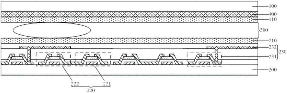
[0049] Therefore, a microfluidic system provided by an embodiment of the present invention, such as Figure 1a shown, including:

[0050] The upper substrate 100 and the lower substrate 200 facing each other form a droplet accommodation space 300 between the upper substrate 100 and the lower substrate 200;

[0051]The first hydrophobic layer 110 located on the outermost surface of the upper substrate 100 facing the droplet accommodation space 300;

[0052] The second hydrophobic layer 210 located on the outermost surface of the lower substrate 200 facing the droplet accommod...


PUM


Abstract

The present invention discloses a microfluidic system and a driving method thereof. A plurality of photosensitive detection units comprising phototransistors and first gating transistors are employed to perform liquid drop position and size detection. The driving method comprises: In a collection time quantum, loading cut-off signals to a first scanning signal line to allow each phototransistor to be a closure state, loading conduction signals to a second scanning line to allow the first gating transistors to be conducted, and determining a liquid drop position through detection of signal difference according to a feature that there is difference in a received light intensity received by the phototransistors according to determination of whether there is liquid drop coverage or not, so that detection is performed based on photosensitivity to avoid signal interference and facilitate improvement of detection precision; and in a driving time quantum, loading conduction signals to a third scanning signal line to allow driving transistors to transmit driving signals to driving electrodes to control motion locus of liquid drops. Driving units and the photosensitive detection units in the microfluidic system all employ transistors with no need for arrangement of other detection devices so as to improve manufacturing efficiency.

Description

technical field [0001] The invention relates to the field of micro-control technology, in particular to a micro-fluid control system and a driving method thereof. Background technique [0002] Microfluidic systems are currently used in many fields, especially in chemistry and medicine. Microfluidic systems have unparalleled advantages for various chemical experiments. At present, the microfluidic system generally detects the position and size of the droplet by detecting the impedance, and then controls the driving electrode through the switching transistor to control the trajectory of the droplet. Therefore, a device for detecting impedance needs to be separately provided in the microfluidic system, which makes the fabrication of the microfluidic system more complicated. Moreover, when detecting impedance, it is easy to be interfered by signals, which is not conducive to the accuracy of detection. Contents of the invention [0003] In view of this, an embodiment of the ...

Claims


Application Information

Patent Timeline
Patent Type & Authority Applications(China)
IPC IPC(8): G09G3/34
CPCG09G3/344H01L31/112B01L2200/0673B01L2300/0654B01L2300/0887B01L2300/165B01L2300/0645B01L3/502715B01L2400/0427B01L3/502792H01L31/1126B81B1/00B81B2201/058B01L2200/02B01L3/5027G01N27/44721H10K59/60
Inventor 曹学友董学王海生丁小梁刘英明韩艳玲郭玉珍王鹏鹏郑智仁张平刘伟邓立凯李扬冰
Owner BOE TECH GRP CO LTD
Why Eureka
Try Eureka