Liquid crystal display device with touch panel and method for manufacturing such liquid crystal display device
A liquid crystal display device, touch panel technology, applied in the input/output process of data processing, instruments, polarizing elements, etc., can solve the problem of inability to obtain front contrast, and achieve the effect of excellent front contrast
- Summary
- Abstract
- Description
- Claims
- Application Information
AI Technical Summary
Problems solved by technology
Method used
Image
Examples
preparation example Construction
[0324] The thickness of the film can be prepared by adjusting the solid concentration contained in the dope, the slit gap of the nozzle of the die, the extrusion pressure from the die, the speed of the metal support, etc. so as to obtain a desired thickness. The width of the transparent resin film obtained as described above is preferably in the range of 0.5 to 4 m, more preferably in the range of 0.6 to 3 m, and even more preferably in the range of 0.8 to 2.5 m. The length is preferably wound in the range of 100 to 10,000 m per roll, more preferably in the range of 500 to 9,000 m, and still more preferably in the range of 1,000 to 8,000 m.
[0325] The optical compensation film involved in the present invention can achieve desired optical properties by properly adjusting the process conditions such as the polymer structure used, the type and amount of additives, stretching ratio, and residual volatile components during peeling.
[0326] The optical compensation film according...
Embodiment 1
[0433] As the cellulose ester-based resin, cycloolefin-based resin, polyimide-based resin, polyarylate-based resin, and acrylic resin used in Examples, resins listed below were used.
[0434] [resin]
[0435] Cycloolefin-based resin (COP): ARTON G7810, manufactured by JSR Corporation
[0436] Cellulose acetate propionate (CAP): acetyl substitution degree 1.5, propionyl substitution degree 1.0, total acyl substitution degree 2.5, weight average molecular weight 250,000)
[0437] Polyimide-based resin (PI): A polyimide-based resin was synthesized by the following method.
[0438]
[0439] (polymerization of polyimide precursor)
[0440] Production of polyamic acid using a reactor equipped with a stainless steel separable flask as a reaction vessel, 2 paddle fins as a stirring device in the separable flask, and a device with a cooling capacity of 20.9 kJ / min as a cooling device . During the polymerization reaction, in order to prevent the incorporation of moisture, nitrogen...
Embodiment 2
[0561]
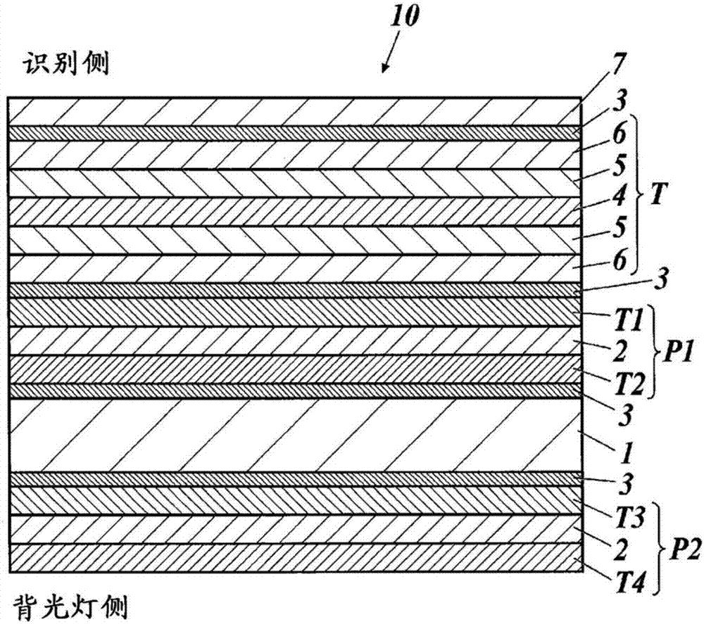
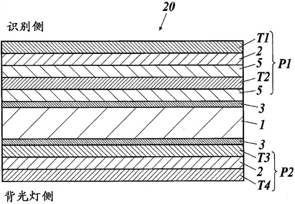
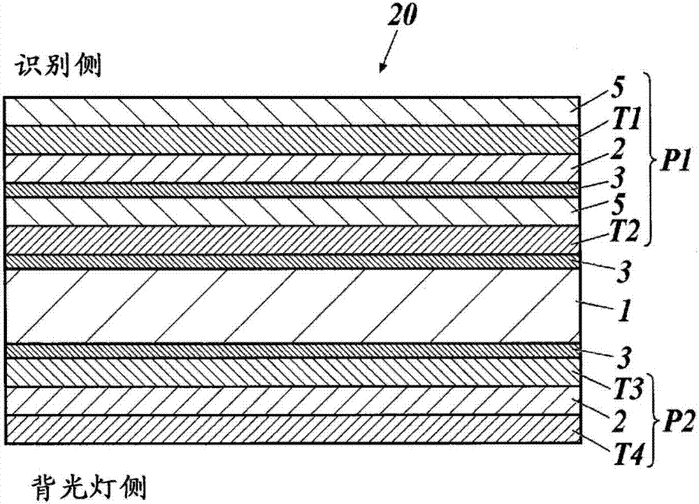
[0562] One side of the optical compensation films 104, 110, 112 and 114 related to the present invention made in Example 1 is formed with an ITO film as a transparent conductive layer with a thickness of 20 nm by the sputtering method, and forms the first layer in the X direction by etching. 1 electrode pattern.
[0563] Next, as an insulating layer arranged between the electrode patterns, SiO 2 A film was formed, an ITO film was formed thereon by sputtering so as to have a thickness of 20 nm, and a second electrode pattern was formed in the Y direction by etching. Furthermore, SiO was sputtered to a thickness of 200nm 2 Formed into a film as an insulating layer. Next, heat treatment (annealing) was performed at 150° C. for 30 minutes to lower the resistance value, and optical compensation films 201 to 204 having transparent conductive layers corresponding to optical compensation films 104 , 110 , 112 , and 114 were produced.
[0564] Image 6 >
[0565] The pol...
PUM
| Property | Measurement | Unit |
|---|---|---|
| Glass transition temperature | aaaaa | aaaaa |
| Thickness | aaaaa | aaaaa |
| Roughness | aaaaa | aaaaa |
Abstract
Description
Claims
Application Information
 - R&D
- Intellectual Property
- Life Sciences
- Materials
- Tech Scout
- Unparalleled Data Quality
- Higher Quality Content
- 60% Fewer Hallucinations
Browse by: Latest US Patents, China's latest patents, Technical Efficacy Thesaurus, Application Domain, Technology Topic, Popular Technical Reports.
© 2025 PatSnap. All rights reserved.Legal|Privacy policy|Modern Slavery Act Transparency Statement|Sitemap|About US| Contact US: help@patsnap.com


