Centrifugal compressor

A technology of centrifugal compressor and diffuser, which is applied in the direction of mechanical equipment, machine/engine, liquid fuel engine, etc., can solve the problems that affect the reliability of compressor operation, the range of cooling is limited, and the overheating loss is serious. Heat flow, reduce the cooling range, and the effect of sufficient heat exchange

Pending Publication Date: 2018-01-05
GREE ELECTRIC APPLIANCES INC
View PDF4 Cites 1 Cited by
  • Summary
  • Abstract
  • Description
  • Claims
  • Application Information

AI Technical Summary

Problems solved by technology

However, the range of cooling through this air supply method is limited. At this time, the mixed refrigerant still has a high degree of superheat, which has not reached or approached the ideal dry saturation state, and the superheat loss is still relatively serious; and it is separated from the flasher. The flash steam that comes out is often a refrigerant in a mixed state of vapor and liquid. When the heat exchange is insufficient, it is easy to cause part of the refrigerant entering the next stage of compression to still be in the state of liquid droplets, and the phenomenon of "air supplementation with liquid" occurs. Convection channel And the impeller of the next stage forms a liquid impact, which affects the reliability of the compressor operation

Method used


Image

  • Centrifugal compressor
  • Centrifugal compressor
  • Centrifugal compressor

Examples


Embodiment Construction

[0033] In order to make the objectives, technical solutions, and technical effects of the present invention clearer, the following describes specific embodiments of the present invention with reference to the accompanying drawings. It should be understood that the specific embodiments described here are only used to explain the present invention, but not to limit the present invention.

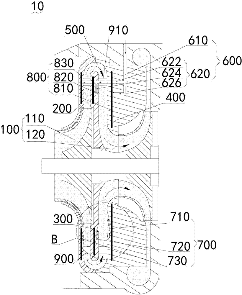
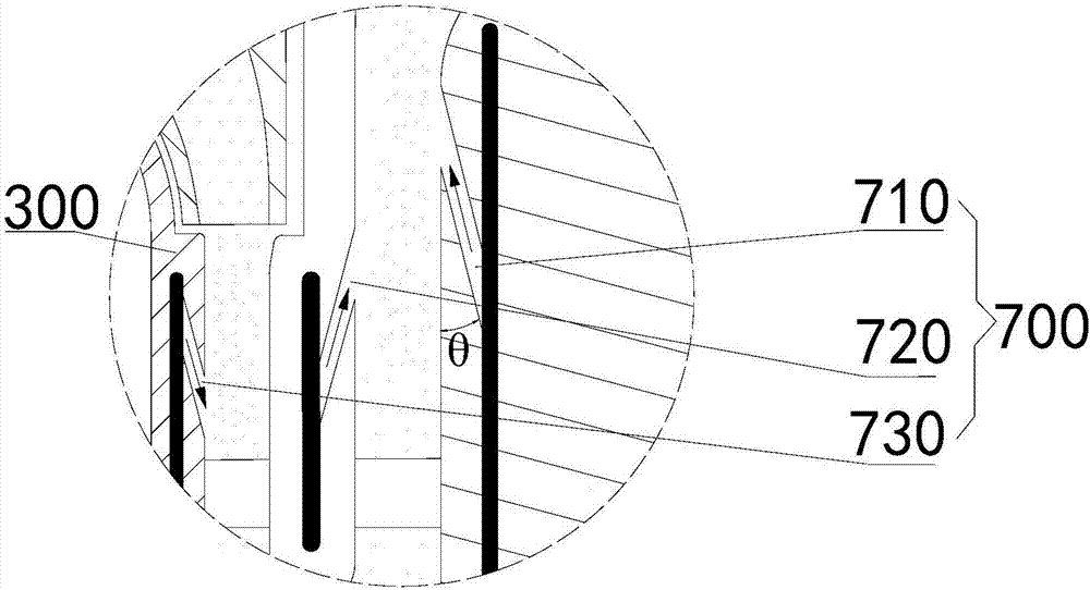
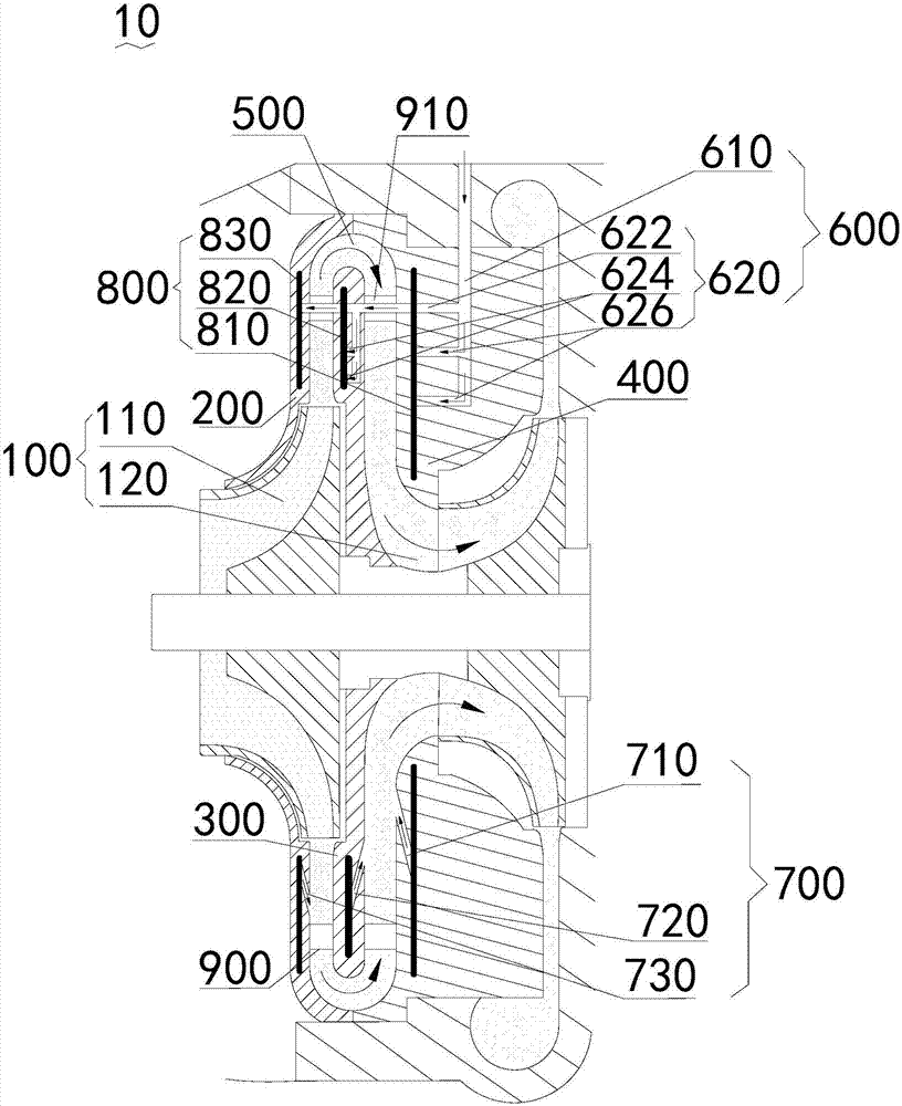
[0034] See figure 1 , The present invention provides a centrifugal compressor 10, which includes at least two stages of impeller 100, a diffuser 200, a return flow plate 300 and a return 400. The diffuser 200, the return flow plate 300 and the return flow device 400 form a stage flow channel 500 connecting the two stages of the impeller 100. The centrifugal compressor 10 also includes a supplemental air passage. The air supplement channel includes an air supplement port 600, an air outlet 700, and a cooling channel 800. The cooling channel 800 is disposed inside at least one of the diffuser 200...


PUM


Abstract

The invention provides a centrifugal compressor, which comprises at least two stages of impellers, a pressure expander, a return channel transition plate and a return channel. The pressure expander, the return channel transition plate and the return channel form a stage runner for communicating the two stages of impellers. The centrifugal compressor further comprises a gas supply channel, which comprises a gas supply port, a gas outlet and a cooling channel. The cooling channel is arranged in at least one of the pressure expander, the return channel transition plate and the return channel; thegas outlet communicates with the stage runner; and a replenishing medium enters from the gas supply port, flows through the cooling runner, flows out from the gas outlet, enters the stage runner, andis mixed with gas in the stage runner.

Description

Technical field [0001] The invention relates to the technical field of compression equipment, in particular to centrifugal compressors. Background technique [0002] Because the specific volume ν of the gas at high temperature is very large, and the temperature of the refrigerant gas in the compressor will rise sharply after being compressed, the energy consumption of the compressor will increase sharply when the unit has the same cooling capacity. In order to reduce compressor power consumption and improve refrigeration efficiency, multi-stage compression refrigeration cycle systems are often used. The most widely used at present is the "two-stage compression intermediate incomplete cooling refrigeration cycle system" with a flash steam separator (commonly known as an economizer or flash generator). [0003] In the traditional two-stage compression refrigeration cycle system, the flash steam separated from the flash generator enters the stage runner directly from the gas inlet to...

Claims


Application Information

Patent Timeline
Patent Type & Authority Applications(China)
IPC IPC(8): F04D17/10F04D29/42F04D29/58
Inventor 欧阳鑫望周义钟瑞兴蒋楠蒋彩云陈玉辉刘增岳雷连冬陈健
Owner GREE ELECTRIC APPLIANCES INC
Why Eureka
Try Eureka