Multi-frequency base station antenna for eliminating coupling resonance

A technology for eliminating coupling and base station antennas, which is applied in independent antenna unit combinations, antennas, antenna couplings, etc., can solve problems such as cross polarization deterioration, horizontal plane pattern distortion, and high-frequency radiation unit size is too large, and achieves the implementation method Simple, eliminate coupling resonance, and improve the effect of isolation

Active Publication Date: 2018-01-05
COMBA TELECOM TECH (GUANGZHOU) CO LTD
View PDF7 Cites 17 Cited by
  • Summary
  • Abstract
  • Description
  • Claims
  • Application Information

AI Technical Summary

Problems solved by technology

However, this method does not work for low-frequency (690-960MHz) systems with relatively long wavelengths. There is not much space inside the multi-frequency base station antenna to open the low-frequency array spacing
Adding a metal plate higher than the radiation surface of the vibrator between the two low-frequency array systems can also weaken the coupling of the radiation field between the arrays and improve the isolation between the systems, but this method seriously affects the radiation pattern of the array, resulting in Cross-polarization deterioration and horizontal pattern distortion
The solutions in the prior art are as follows: (1) Eliminate the isolation resonance interference caused by the mutual coupling between the high frequency and low frequency by specially designing the high frequency and low frequency oscillator units, but when the high frequency oscillator When the unit deviates from the optimal design size, that is, the size of the high-frequency radiation unit is too large or too small, its performance will be reduced
(2) In a decoupling slot unit loaded between two columns of low-frequency radiation arrays with a periodically arranged structure, this decoupling slot boundary can only be applied without any radiation unit between the two columns of radiation units, and Only suitable for working in the same frequency band MIMO array antenna
(3) An array antenna working at double high frequencies plus a low frequency, its function is to improve the beam convergence characteristics, block the mutual coupling between the high frequency and low frequency arrays, thereby affecting the low frequency beam convergence characteristics, but it is not suitable for Work in more systems Multi-frequency antenna especially two high frequency plus two low frequency above side by side array layout
[0008] All in all, for a base station antenna with two low-frequency radiation arrays on the left and right and a high-frequency radiation array arranged side-by-side in the middle, or a side-by-side array layout of two high-frequency plus two low-frequency arrays, in the prior art, The technical problems of eliminating resonance and using high and low frequency coupling to improve the radiation performance of the low frequency radiation array cannot be solved at the same time

Method used


Image

  • Multi-frequency base station antenna for eliminating coupling resonance
  • Multi-frequency base station antenna for eliminating coupling resonance
  • Multi-frequency base station antenna for eliminating coupling resonance

Examples


Embodiment 1

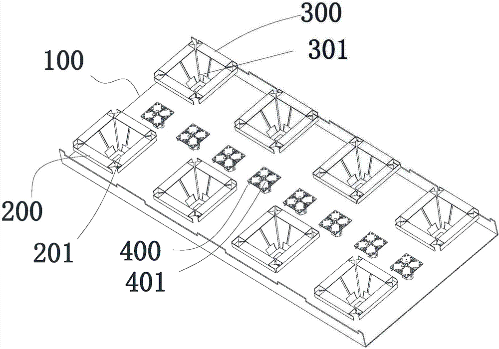
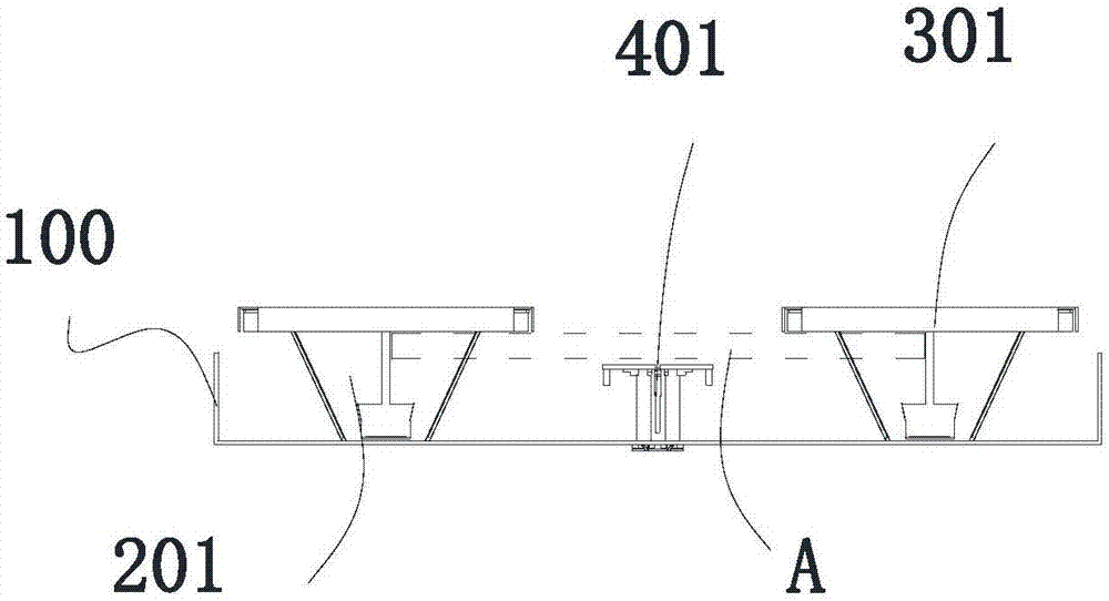
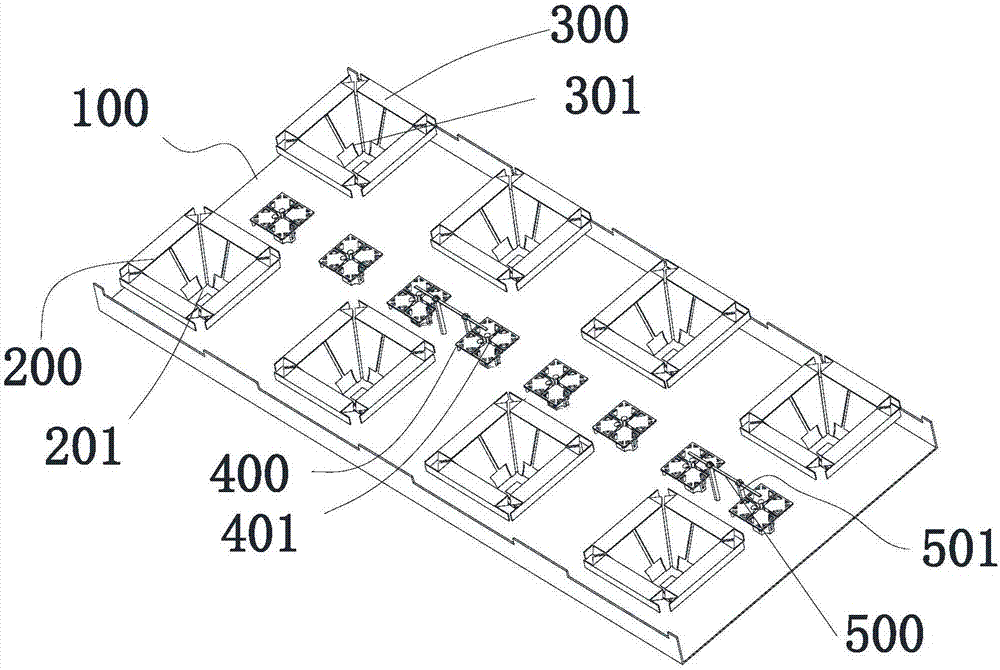
[0042] Embodiment 1, within the scope of the above-mentioned dotted frame area A, the spacer 500 is used to eliminate part of the coupling mutual impedance Z t , which is located in the upper space of the first high-frequency radiation array 400 in the middle position, such as Figure 3-4 shown. The spacer 500 can eliminate the coupling field Z between the first high-frequency radiation array 400 and the first and second low-frequency radiation arrays 200 and 300 21 , thereby improving the radiation performance of the first high-frequency radiation array 400 and the first and second low-frequency radiation arrays 200 and 300, reducing the generation of resonance between the arrays, and improving the isolation between the arrays. The width of the spacer strip 500 is 0.01-0.05 times the wavelength of the low-frequency resonance frequency point, and the distance between it and the reflector 100 is 0.2-0.25 times the wavelength of the low-frequency resonance frequency point. The...

Embodiment 2

[0043] Embodiment 2, within the area A of the dotted line frame above, the spacer strip 500 is located below the inner dipole arms of the first and second low-frequency radiation units 201 and 301 , and on the side of the first low-frequency radiation unit 201 . Between the dipole arm and the adjacent dipole arm of the first high-frequency radiation unit 401 or between the dipole arm of the second low-frequency radiation unit 301 and the dipole arm of the first high-frequency radiation unit 401, such as Figure 5-6 shown. In this specific embodiment, the parasitic coupling introduced by the spacer bar 500 is used to change the current distribution of the vibrator, thereby changing the radiation impedance Z of the resonant frequency point of the first and second low-frequency radiation arrays 200 and 300 r = R r The reactive component jX of +jX changes the coupling field Z between the first high-frequency radiation array 400 and the first and second low-frequency radiation arr...

Embodiment 3

[0049]Embodiment 3 can be used in combination with Embodiment 1 or 2 respectively, or the three embodiments can be used in combination at the same time, thereby reducing the impact on the first high-frequency radiation array 400 or the first and second low-frequency radiation arrays 200, 300 , the combined use of the three schemes will not interfere with each other, and both can achieve the purpose of eliminating coupling resonance.

[0050] The array structure of the base station antenna of the present invention is not limited to such as Figure 3-8 The shown combination of arrays—only the first high-frequency radiation array 400 and the first and second low-frequency radiation arrays 200 and 300 are parallel to each other. In Embodiment 4, the multi-frequency base station antenna that eliminates coupling resonance also includes a second high-frequency radiation unit 700 nested in the first and second low-frequency radiation units 201, 301 and adjacent same-array A third hig...


PUM


Abstract

The invention provides a multi-frequency base station antenna for eliminating coupling resonance. The multi-frequency base station antenna comprises a reflecting plate, a first low-frequency radiationarray, a second low-frequency radiation array and a first high-frequency radiation array, wherein the first low-frequency radiation array and the second low-frequency radiation array are arranged onthe reflecting plate, are parallel to each other and are arranged on the same radiation surface, the first high-frequency radiation array is arranged between the first low-frequency radiation array and the second low-frequency radiation array, the first low-frequency radiation array and the second low-frequency radiation array respectively comprises a plurality of low-frequency radiation units, the first high-frequency radiation array comprises a plurality of first high-frequency radiation arrays, the multi-frequency base station antenna also comprises isolation strips, and the isolation strips are parallel to the reflecting plate, are insulated with the reflecting plate, extend along central axes of the first low-frequency radiation array and the second low-frequency radiation array and are arranged between radiation surfaces of the first high-frequency radiation units and radiation surfaces of the first low-frequency radiation units and the second low-frequency radiation units. By the multi-frequency base station antenna, coupling among the arrays is reduced, and the technical effects of improving the isolation among the arrays and reducing resonances among the arrays are achieved.

Description

technical field [0001] The invention relates to the field of communication base station antennas, in particular to a multi-frequency base station antenna for eliminating coupling resonance between different systems in a multi-frequency antenna array. Background technique [0002] The main transmission path of electromagnetic interference between radio systems is the coupling between antennas. Isolation is often used to quantitatively characterize the strength of this coupling, which is defined as the ratio of the power transmitted by one antenna to the power received by the other antenna, expressed in dB. [0003] With the increase of mobile communication network standards, base station antennas are required to support multiple communication systems. In order to save site and antenna resources, reduce the difficulty of property coordination, and reduce investment costs, multi-frequency antennas that can support multi-system communications have gradually become an operational...

Claims


Application Information

Patent Timeline
Patent Type & Authority Applications(China)
IPC IPC(8): H01Q1/52H01Q19/10H01Q21/30
Inventor 王灿陈强王强贾飞飞
Owner COMBA TELECOM TECH (GUANGZHOU) CO LTD
Why Eureka
Try Eureka