
Intelligent safety helmet communication system

A communication system and safety helmet technology, applied in the field of communication systems, can solve problems such as short communication distance, high power consumption of GPS chips, and single function, so as to achieve the effect of reducing power consumption and providing feasibility

Pending Publication Date: 2018-01-05
常州全橙智能科技有限公司
View PDF0 Cites 4 Cited by
  • Summary
  • Abstract
  • Description
  • Claims
  • Application Information

AI Technical Summary

Problems solved by technology

The smart helmets involved in the market first use wireless wifi, bluetooth or zigbee, or GPRS for wireless communication. The former has a short communication distance and poor coverage, and is dependent on gateways and supporting terminal equipment. The latter communication method is the second generation. Network technology, GSM network will also gradually withdraw from the network and frequency; secondly, the function of the positioning module is mainly GPS positioning, with a single function, and it cannot provide multiple methods or combinations in different signal coverage environments to realize the positioning of the wearing state of the smart helmet Function
[0003] Disadvantages of the existing technology: 1. The means of communication are backward, such as GPRS, and the network has the risk of disconnecting from the network; 2. It is dependent on the gateway terminal equipment; 3. The traditional positioning method relies on an independent GPS chip, which consumes a lot of power and requires frequent Replace the battery or charge to maintain the use, and cannot be linked with whether the helmet is worn correctly and record the location information, or need to build an independent functional receiver to obtain GPS signals to achieve location positioning

Method used


Image

  • Intelligent safety helmet communication system

Examples


Embodiment Construction

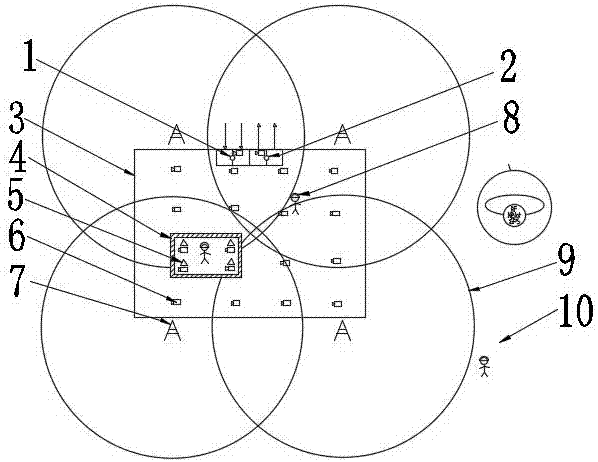
[0022] Such as figure 1 It is a schematic diagram of the structure of the present invention, a smart helmet communication system, including an electronic fence 3 and an operator base station 7, and the signal of the operator base station 7 covers the area of ​​the electronic fence 3, and the electronic fence 3 is equipped with an entry access control 1 and an exit access control 2, The smart safety helmet 8 worn by the staff is connected with the base station 7 of the operator.

[0023] When this smart helmet communication system is in use, the staff who enter the electronic fence 3 are recorded through the position of the entrance guard 1 on the electronic fence 3, and the recording method is the smart helmet worn by the staff The identification chip in 8 is matched with the identifier of entry access control 1 to realize the recording of the staff entering the work area, and at the same time, the identification chip in the smart helmet 8 of the outgoing staff is also install...


PUM


Abstract

The invention relates to the technical field of communication systems, in particular to an intelligent safety helmet communication system. The intelligent safety helmet communication system includes an electronic fence and an operator base station. The signal of the operator base station covers the area of the electronic fence. The electronic fence is provided with an entrance door access and an exit door access. Intelligent safety helmets worn by staff are connected with the operator base station. This intelligent safety helmet communication system has the following advantages: 1, the systemmakes up for the deficiency that the traditional IOT communication needs to set up a separate receiver (base station); 2, a variety of communication positioning technologies are combined to optimize the management mode of the construction staff; 3, the communication function in a signal-free area is achieved; 4, while positioning through the Nbiot base station, GPS assistance can be achieved by analgorithm to provide more precise positioning; 5, the data of communication feedback parameters is quantified, which provides the feasibility of digitizing system integration.

Description

technical field [0001] The invention relates to the technical field of communication systems, in particular to an intelligent helmet communication system. Background technique [0002] There are currently no products with the same or similar functions on the market. The smart helmets involved in the market first use wireless wifi, bluetooth or zigbee, or GPRS for wireless communication. The former has a short communication distance and poor coverage, and is dependent on gateways and supporting terminal equipment. The latter communication method is the second generation. Network technology, GSM network will also gradually withdraw from the network and frequency; secondly, the function of the positioning module is mainly GPS positioning, with a single function, and it cannot provide multiple methods or combinations in different signal coverage environments to realize the positioning of the wearing state of the smart helmet Features. [0003] Deficiencies of the existing tech...

Claims


Application Information

Patent Timeline
IPC IPC(8): H04W4/00H04W4/02A42B3/30G07C9/00
Inventor 赵春章佳音
Owner 常州全橙智能科技有限公司
Learn More