Eureka AIR delivers breakthrough ideas for toughest innovation challenges, trusted by R&D personnel around the world.

Centrifugal blood pump which rotates stably

A kind of painstaking and stable technology, applied in medical science, prosthesis, etc., can solve the problems of lack of mechanical positioning structure, affecting blood function, destroying plasma, etc., to prolong the life of blood pump, reduce energy consumption, and reduce wear and tear.

Pending Publication Date: 2018-01-09
美茵(北京)医疗器械研发有限公司 +1
View PDF1 Cites 9 Cited by
  • Summary
  • Abstract
  • Description
  • Claims
  • Application Information

AI Technical Summary

Problems solved by technology

[0004] The current common structure of centrifugal blood pump is the centrifugal blood pump disclosed in Chinese patent ZL201380053302.9, which adopts a centrifugal blood pump that is light in weight and can provide high torque on the impeller, wherein the impeller is axially and radially centered without any mechanical Bearing, this is a typical centrifugal magnetic levitation heart pump; although this structure reduces mechanical wear and improves the mechanical performance of the impeller, there are still a series of problems in actual use; the impeller of this type of structure lacks a mechanical positioning structure, and the low speed The rotation stability is poor, and its control generally adopts a high speed with high inertia and stability. However, the blade at a high speed will destroy the blood plasma and affect the function of the blood. control method; in addition, the magnetic levitation structure also needs additional energy supply, and its energy consumption is also high

Method used


Image

  • Centrifugal blood pump which rotates stably
  • Centrifugal blood pump which rotates stably
  • Centrifugal blood pump which rotates stably

Examples


Embodiment Construction

[0020] The specific embodiments of the present invention will be further described below in conjunction with the accompanying drawings.

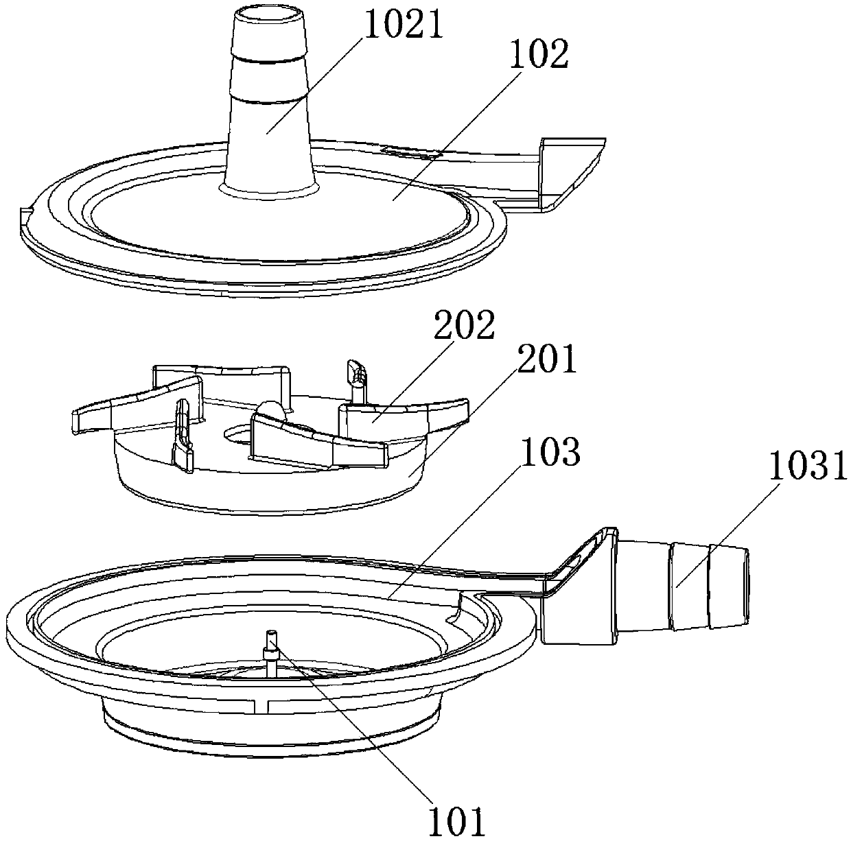
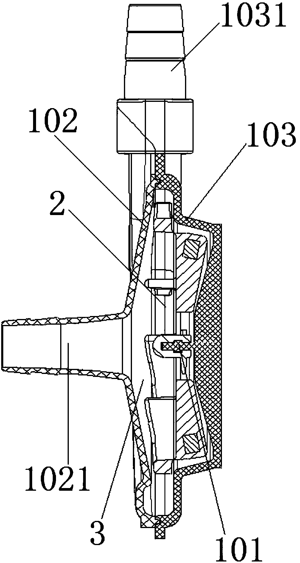
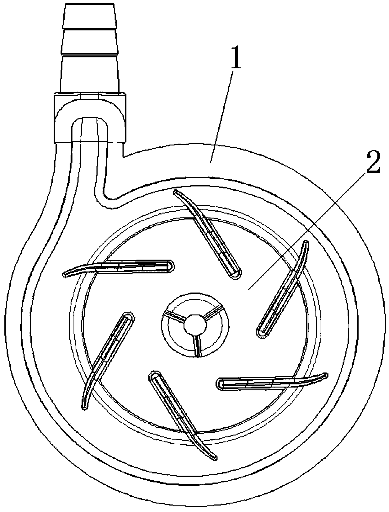
[0021] Such as Figure 1-3 As shown, the present invention is realized in such a way that the centrifugal blood pump with stable rotation includes a housing 1 and an impeller 2 installed in the housing 1, and its structural feature is that the center of the housing 1 is facing the impeller 2 The positioning shaft 101 matched with the central hole of the impeller 2; compared with the traditional suspension type or centrifugal blood pump without a fixed shaft, the present invention can still work smoothly and normally at the low speed of the impeller 2, and the impeller 2 rotates more smoothly Smooth and reliable; using the low-speed characteristics of the centrifugal blood pump, blood can be pumped out at low pressure, reducing the damage to plasma caused by the high-speed rotation of the impeller 2 and excessive working pressure during the b...


PUM


Abstract

The invention provides a centrifugal blood pump which rotates stably. The centrifugal blood pump comprises a shell and an impeller installed in the shell, and the portion, right facing the center of the impeller, of the shell is provided with a locating shaft matched with a center hole of the impeller; the impeller is installed in the center of a spiral type blood channel between an upper cover and a lower cover; the upper cover and the lower cover are provided with a blood inflow pipe and a blood outflow pipe which are communicated with the blood channel respectively; blades in the impeller comprise main blades and subsidiary blades connected to the outer end of the main impellers; the main blades are uniformly distributed along the circumference of a rotor, and the included angles between the main blades and the blood rotating and circulating direction of the blood channel are obtuse angles. Through the optimized designed impeller and the relevant structural design, the centrifugal blood pump has high pumping efficiency at a low rotation speed, the blood arterial pressure is guaranteed, the low rotation speed lowers wear, the service life of the blood pump is prolonged, the energy consumption is also lowered, the cruising capability of the blood pump is improved, the low rotation speed also lowers the control difficulty of the work pressure of the blood pump, and the centrifugal blood pump is also simpler and more convenient to use and operate.

Description

technical field [0001] The invention relates to a centrifugal blood pump, in particular to a centrifugal blood pump with stable rotation. Background technique [0002] Blood pump is a kind of blood supply auxiliary equipment. It relies on pneumatic, electric or magnetic power to make blood pressure difference to drive blood circulation supply flow. It is mainly used for total artificial heart and ventricular function assistance. [0003] At present, the more commonly used blood pump is the centrifugal blood pump, which is to install the blades on the rotor of the blood pump. When the rotor rotates at a high speed, these blades will guide the blood and throw it to the outer edge, and the dynamic action of the blades on the blood will form an artery. Pressure, thereby driving blood circulation to pump out, the size of the arterial pressure depends on the speed of the impeller, generally speaking, the higher the speed, the higher the arterial pressure and the faster the blood f...

Claims


Application Information

Patent Timeline
IPC IPC(8): A61M1/10
Inventor 刘鸿箫顾承雄尤斌凌云鹏方颖李红武
Owner 美茵(北京)医疗器械研发有限公司
Why Eureka
Eureka Blog
Learn More