Luminescence device and related projection system and illumination system
A technology of light-emitting device and wavelength conversion device, applied in projection devices, optics, instruments, etc., can solve the problems of easy occurrence of thermal quenching and high energy density of excitation light, and achieve the effect of reducing energy density and thermal quenching phenomenon.
- Summary
- Abstract
- Description
- Claims
- Application Information
AI Technical Summary
Problems solved by technology
Method used
Image
Examples
Embodiment 1
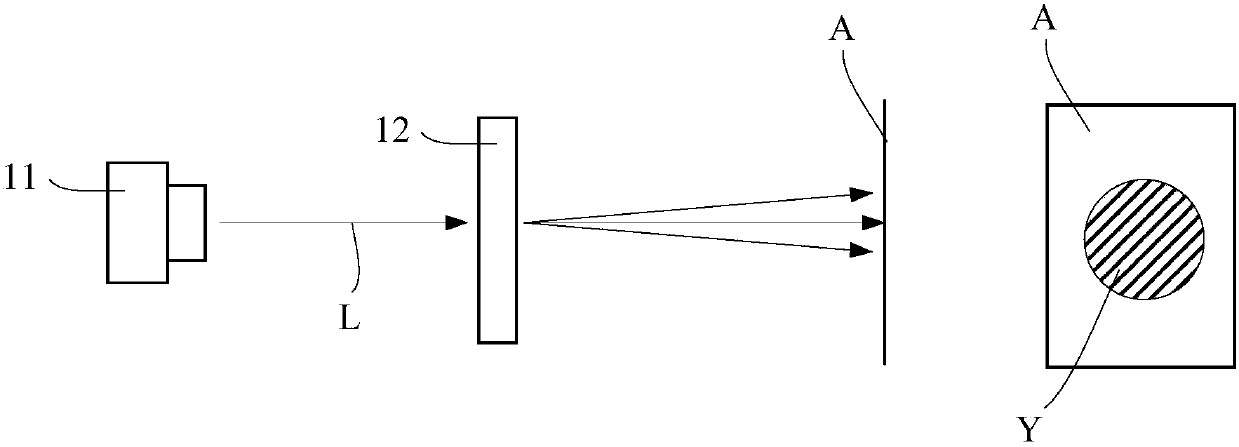
[0063] According to the above experimental findings and principle analysis, the present invention proposes a light emitting device. see Figure 7 , Figure 7 It is a structural schematic diagram of an embodiment of the light emitting device in the embodiment of the present invention. Such as Figure 7 As shown, the light emitting device 700 includes a light source 710 and a surface scattering sheet 720 .
[0064] The light source 710 is preferably a laser, and may also be other light-emitting elements or components, as long as it can provide incident light L1 with a small divergence angle.
[0065] Structural Reference of Surface Scattering Sheet 720 image 3 instruction of. The light L1 from the light source 710 is incident on the surface scattering sheet 720 , and the light L1 may be incident on the plane surface of the surface scattering sheet 720 or may be incident on the rough surface of the surface scattering sheet 720 . The surface scattering sheet 720 is used to ...
Embodiment 2
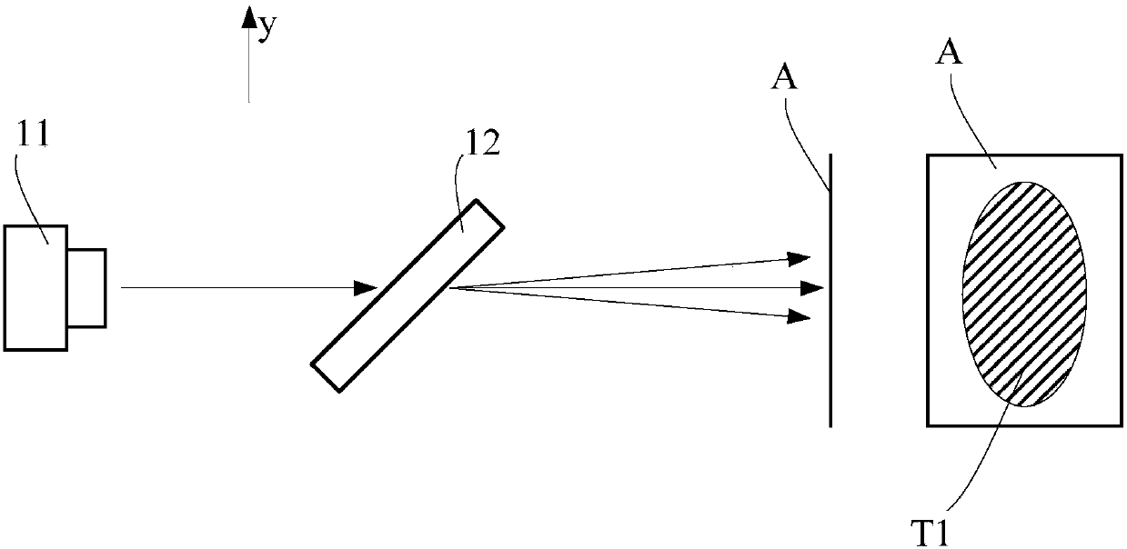
[0071] see Figure 8a and Figure 8b , Figure 8a is a schematic structural view of another embodiment of the light emitting device in the embodiment of the present invention, Figure 8b yes Figure 8a Schematic diagram of the inlet of the integrating rod viewed from the x direction in the examples. Such as Figure 8a and 8b As shown, the light emitting device 800 includes a light source 810 and a surface scattering sheet 820 , and the incident light L1 emitted by the light source 810 is obliquely incident on the surface scattering sheet 820 . The light-emitting device also includes an integrator rod 830 located at the rear end of the light path of the surface scattering sheet 820. The optical axis of the light emitted by the surface scattering sheet 820 is the horizontal direction of the paper, the entrance plane of the integrating rod is perpendicular to the optical axis, and the long side direction of the integrating rod entrance 831 Parallel to the vertical direction...
Embodiment 3
[0075] see Figure 9a and Figure 9b , Figure 9a is a schematic structural view of another embodiment of the light emitting device in the embodiment of the present invention, Figure 9b yes Figure 9a Schematic diagram of the wavelength conversion device viewed from the x-direction in the examples. Such as Figure 9a and 9b As shown, the light emitting device 900 includes a light source 910 and a surface scattering sheet 920 , and the incident light L1 emitted from the light source 910 is obliquely incident on the surface scattering sheet 920 . The light-emitting device also includes a wavelength conversion device 930. The light scattered by the surface scattering sheet 920 is incident on the wavelength conversion device, and the optical axis of the light emitted by the surface scattering sheet 920 is perpendicular to the wavelength conversion device. The diameter D of the wavelength conversion device is the vertical direction.
[0076] The wavelength conversion device...
PUM
| Property | Measurement | Unit |
|---|---|---|
| Angle of incidence | aaaaa | aaaaa |
Abstract
Description
Claims
Application Information
 - R&D
- Intellectual Property
- Life Sciences
- Materials
- Tech Scout
- Unparalleled Data Quality
- Higher Quality Content
- 60% Fewer Hallucinations
Browse by: Latest US Patents, China's latest patents, Technical Efficacy Thesaurus, Application Domain, Technology Topic, Popular Technical Reports.
© 2025 PatSnap. All rights reserved.Legal|Privacy policy|Modern Slavery Act Transparency Statement|Sitemap|About US| Contact US: help@patsnap.com


