A system and method for increasing the data transmission rate of a vector network analyzer

A vector network analysis, data transmission rate technology, applied in transmission systems, electrical digital data processing, instruments, etc., can solve the problems of reduced bus effective bandwidth, slow data transmission rate, complicated system hardware connection, etc., to improve the data transmission rate. and efficiency, improving robustness and cost-effectiveness, and reducing manufacturing costs

Active Publication Date: 2020-02-14
THE 41ST INST OF CHINA ELECTRONICS TECH GRP
View PDF4 Cites 0 Cited by
  • Summary
  • Abstract
  • Description
  • Claims
  • Application Information

AI Technical Summary

Problems solved by technology

[0005] 1) The PCI bus used by the current desktop vector network analyzer needs to adopt the design method of time-division multiplexing of address lines and data lines when connecting multiple devices. Each device needs to initiate a request to the host to occupy the bus bandwidth and get a response from the host. Only after the bus can be occupied, the effective bandwidth of the bus is greatly reduced, and the transmission rate is slowed down; and the clock of the PCI bus is limited to the slowest peripheral among multiple peripherals, which seriously restricts the performance of high-speed peripherals on the bus. Play, poor bus scalability;
[0006] 2) The PCI bus can only perform one-way data transmission at each moment, and the sending and receiving of data needs to be carried out in time-sharing, which increases the waiting time and leads to slow data transmission rate;
[0007] 3) The PCI bus used by the vector network analyzer is a parallel architecture, and the number of parallel data lines and address lines is large, so that the number of pins of the internal communication interface of the instrument is large, and the system hardware connection is more complicated, so the hardware manufacturing cost is higher

Method used


Image

  • A system and method for increasing the data transmission rate of a vector network analyzer

Examples


Embodiment Construction

[0044] The present invention will be further described below in conjunction with the accompanying drawings and specific embodiments.

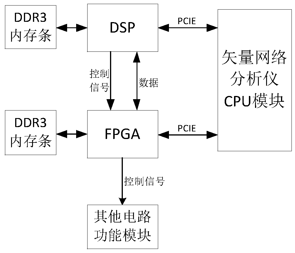
[0045] The invention discloses a system for improving the data transmission rate of a vector network analyzer, such as figure 1 shown, including:

[0046] CPU module, DSP module and FPGA module. The CPU module of the vector network analyzer is connected to the DSP module and the FPGA module respectively through two independent PCIE bus links.

[0047] The PCIE bus of the present invention adopts the popular point-to-point topology in the industry at present. Compared with the shared parallel architecture of the PCI bus and earlier computer buses, each device on the PCIE bus is connected to the root system by a separate serial link ( Host), without requesting bandwidth from the entire bus, can increase the data transfer rate to a very high frequency, reaching the high bandwidth that PCI cannot provide.

[0048] The DSP module and the FPGA mod...


PUM


Abstract

The invention discloses a system and method for improving the data transmission rate of a vector network analyzer, comprising: a CPU module, a DSP module and an FPGA module; the DSP module is connected to the FPGA module, and the CPU module is connected to the FPGA module through a PCIE bus link respectively The DSP module and the FPGA module realize full-duplex high-speed data communication; the CPU module judges whether the PCIE device to be accessed is a DSP module or an FPGA module according to user requirements and thread scheduling in the CPU, and then communicates with the PCIE device to be accessed through the PCIE bus. quick access. The invention has beneficial effects: the time-division multiplexing and shared bandwidth structure of the internal bus of the vector network analyzer is changed to a point-to-point topology, the host of the instrument and each PCIE device have separate communication links, and each PCIE device can be independent Bandwidth sharing, effectively improving the bus bandwidth of the vector network analyzer, while reducing the complexity of the arbitration logic of the instrument's internal controller.

Description

technical field [0001] The invention relates to a system and method for increasing the data transmission rate of a vector network analyzer. Background technique [0002] The PCI bus is a 33MHz@32bit or 66MHz@64bit parallel bus with a bus bandwidth ranging from 133MB / S to 533MB / S. The PCI host and all devices on the PCI bus share a common set of address, data and control lines, and all devices share the bus bandwidth, which determines that only one device can occupy the bus and communicate with the host at the same time, and other devices during this period Can only wait for the release of the bus. [0003] With the increasing complexity of the application solutions of the vector network analyzer, more and more occasions require the vector network analyzer to be able to perform high-speed and large-bandwidth measurements on the DUT. However, the internal data transmission of the existing vector network analyzer uses the PCI bus, and its low-speed parallel architecture canno...

Claims


Application Information

Patent Timeline
Patent Type & Authority Patents(China)
IPC IPC(8): G06F13/42H04L5/14H04L29/08
Inventor 杨明飞年夫顺梁胜利刘丹袁国平李明太赵立军庄志远
Owner THE 41ST INST OF CHINA ELECTRONICS TECH GRP
Why Eureka
Try Eureka