Quantum dot LED package structure

A technology of LED packaging and quantum dots, which is applied in the direction of electrical components, circuits, semiconductor devices, etc., can solve the problems of difficult liquid crystal display narrow frame display, blue color shift at the edge of backlight, and decrease in fluorescence efficiency, so as to improve luminous efficiency and service life , easy to display with narrow borders, good heat dissipation effect

Active Publication Date: 2018-01-09
SHENZHEN CHINA STAR OPTOELECTRONICS TECH CO LTD
View PDF11 Cites 25 Cited by
  • Summary
  • Abstract
  • Description
  • Claims
  • Application Information

AI Technical Summary

Problems solved by technology

[0005] figure 1 is the absorption spectrum diagram of red light quantum dots and green light quantum dots, figure 2 is the emission spectrum diagram of red light quantum dots and green light quantum dots, figure 1 and figure 2 In the figure, the gray line represents the green light quantum dots, and the black line represents the red light quantum dots, from figure 2 It can be seen from the figure that the half-maximum width (FWHM) of red quantum dots and green quantum dots is very narrow, so adding quantum dots to the light source can greatly improve the color gamut of the liquid crystal display. However, if the quantum dots are exposed to water and oxygen Under the environment, its fluorescence efficiency will decline irreversibly and rapidly, so the encapsulation of quantum dots needs to be well isolated from water and oxygen. In addition, as the temperature rises, the luminous efficiency of quantum dot materials will gradually decrease, and the luminous wavelength will also red-shift, so The packaging of quantum dots needs to be isolated from high temperature or have a better heat dissipation environment
[0006] At present, in the backlight application of quantum dots, the main packaging method of quantum dots is to encapsulate them in glass tubes or in water and oxygen barrier PET films, but the glass used in the former is fragile, and the light utilization rate is low, so it is not easy to realize liquid crystal displays. The narrow bezel display, the latter is prone to blue color cast at the edge of the backlight and has the disadvantage of high cost

Method used


Image

  • Quantum dot LED package structure
  • Quantum dot LED package structure
  • Quantum dot LED package structure

Examples


Embodiment Construction

[0031] In order to further illustrate the technical means adopted by the present invention and its effects, the following describes in detail the preferred embodiments of the present invention and the accompanying drawings.

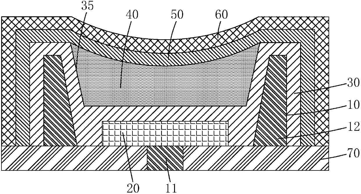
[0032] See image 3 , The present invention provides a quantum dot LED packaging structure, including:

[0033] The non-metal support 10 includes a bottom plate 11 and a side wall 12 connected to the periphery of the bottom plate 11;

[0034] The LED chip 20 is fixed on the bottom plate 11, and the thickness of the LED chip 20 is less than the height of the side wall 12;

[0035] The first barrier layer 30 covers the surface of the sidewall 12, the LED chip 20 and the bottom plate 11, and a groove 35 is formed on the surface of the first barrier layer 30 corresponding to the LED chip 20;

[0036] The quantum dot silica gel layer 40 is arranged in the groove 35;

[0037] The second barrier layer 50 covers the surfaces of the first barrier layer 30 and the quantum do...


PUM


Abstract

The invention provides a quantum dot LED package structure which includes a nonmetal bracket, an LED chip, a first barrier layer, a quantum dot silica gel layer, a second barrier layer, and an undopedsilica gel layer. The quantum dot silica gel layer can improve the color gamut and color saturation of a liquid crystal display. The first barrier layer can radiate the LED chip and stop outside water oxygen from invading the LED chip. The second barrier layer can stop outside water oxygen from invading the quantum dot silica gel layer and the LED chip and achieve a further radiating effect. Thus, the quantum dot LED package structure of the invention provides an environment isolated from water oxygen and having a good radiating effect for quantum dots, and can improve the luminescence efficiency and service life of quantum dots. Compared with the existing quantum dot LED package structure, the quantum dot LED package structure of the invention has high reliability and low production cost, and can help to easily realize a narrow-bezel liquid crystal display.

Description

Technical field [0001] The invention relates to the field of display technology, in particular to a quantum dot LED packaging structure. Background technique [0002] With the development of semiconductor lighting technology, light-emitting diodes (LEDs) as backlights have been widely used in the fields of tablet computers, notebook computers, liquid crystal displays, large-size LCD TVs, and indoor and outdoor lighting. [0003] At present, white light LEDs are commonly used as backlight sources in liquid crystal display devices, and the most common white light LED is the structure of blue light emitting chip plus yellow YAG phosphor. The color saturation of the LCD screen using this LED is low (generally 72% NTSC Color gamut), the color is not bright enough. In order to improve the color saturation, the yellow phosphor is usually changed to red-green (RG) phosphor, but this method can only increase the color gamut by about 25% (90% NTSC color gamut) , Can not meet the new BT.2020...

Claims


Application Information

Patent Timeline
Patent Type & Authority Applications(China)
IPC IPC(8): H01L33/48H01L33/54H01L33/56
Inventor 樊勇
Owner SHENZHEN CHINA STAR OPTOELECTRONICS TECH CO LTD
Why Eureka
Try Eureka